1. Analysis of common capacitor failures causes of reactors and capacitors
The main operating failure of dry-type air-core reactors is insulation breakdown between coil turns. The causes of failure include damp coils or insulation weaknesses, local discharge arc burnout, local overheating insulation breakdown, overvoltage, short circuit caused by small animals, and deformation and damage of coils due to mechanical stress generated by short-circuit current. Similar to common capacitor failures, reactor failures are also closely related to insulation problems. Especially under high voltage conditions, common capacitor failures are similar to insulation breakdown and dielectric degradation of reactors.
1.1 Deterioration of insulation material surface properties
(1) Causes of surface property degradation. This type of defect manifests itself in cracking, powdering, reduced surface properties, and liquid flow of insulation materials at high temperatures. The causes are improper material selection and improper formulation and curing process. The external insulation of dry-type air-core reactors is basically made of epoxy resin with good processability and cured at room or medium temperature. The disadvantage is that the curing speed is closely related to the curing agent, accelerator, and surrounding environment. The same formula and process can produce resin materials with very different performances due to differences in the activity of the curing agent and accelerator, the ambient temperature, and the humidity. Once the curing is not good, there will be a large number of low-molecular genes and incompletely cross-linked molecular chain bonds in the resin material. Under the action of water, light and other substances, they are easily hydrolyzed, re-reacted, and combined, which will lead to cracks and powdering on the insulation surface of the reactor, and the surface performance will be reduced.
Some reactors, especially those cured at room temperature, have defects such as local overheating or poor welds. These resins that seem to have been cured well will flow and re-cure under the action of high temperature (>80℃) [Lingbao Converter Station of Northwest-Central China Network had oily droplets at the bottom of the operating reactor (PLC reactor, operating temperature is about 85℃, as shown in the infrared temperature measurement spectrum in Figure 1) in 2006, when it was put into operation. In fact, it is resin liquid]. Generally speaking, this curing process is permanent and irreversible. Before curing, the resin flows and forms cavitation inside the insulation, which can easily cause inter-turn insulation damage.
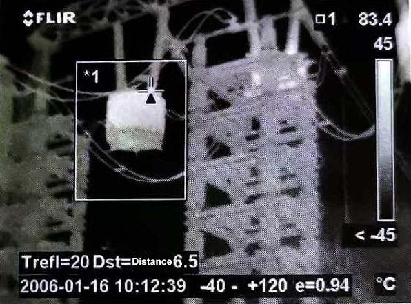
Figure 1 PLC reactor infrared temperature measurement spectrum
Most manufacturers have limited means to control the quality of epoxy resin, and it is even more difficult to adjust the formula according to different batches of epoxy resin. Therefore, the materials and formulas are different, which makes it difficult for the epoxy resin to reach the optimal curing state and leave hidden dangers. The poor compatibility of the topcoat with the substrate will also accelerate surface degradation. Similar to common capacitor failures, due to inconsistent materials or unstable quality, performance degradation and shortened life may also occur.
(2) Treatment measures. Cracking, powdering, and surface performance degradation are all superficial degradation phenomena. Once discovered, they should be treated as soon as possible to avoid development and aggravation to form irreversible degradation. The treatment measures are simple. Use sandpaper to polish and remove deteriorated surface materials such as cracks and powdering, and then clean them carefully. It is best to use anhydrous solvents (such as anhydrous ethanol) for cleaning, and then apply paint or coatings with excellent weather resistance and good compatibility with the base material.
For the problem of resin flow caused by overheating, the only way is to strengthen monitoring, pay special attention to the appearance of small round granular resin materials (i.e. “sweating points”) at the overheating point, and contact the manufacturer as soon as possible to avoid the expansion of the fault.
1.2 Leakage Magnetic Field
(1) Causes of Leakage Magnetic Field. There is a grounding grid in the axial position of the reactor, and there are equipment, fences, frames, etc. in the radial position. All of these may cause serious leakage magnetic problems due to the closed loop formed by the metal body, which is difficult to completely solve on site. Generally speaking, there is only a large ferromagnetic material in the magnetic field range, and there is no closed loop. If there is a closed loop, such as a grounding grid, a frame, a metal fence, etc., the leakage magnetic field will induce a circulating current of hundreds of amperes. This will not only increase the loss, but also cause serious problems due to the coupling of the reverse magnetic field established by it with part of the winding of the reactor. If there is a closed loop in the radial position, the reactor winding will overheat or partially overheat, just like the short circuit of the secondary side of the transformer. If there is a closed loop in the axial position, the reactor current will increase and the potential distribution will change. Therefore, the leakage magnetic problem cannot be simply considered as heat generation or increased loss.
(2) Treatment measures. As long as the closed metal loop is eliminated, such as staying away from metal frames and not using metal fences, this problem can generally be solved. The more difficult thing is to avoid closed loops in the grounding grid and cement components. Before installation, check whether the installation point is in a closed grounding grid or a cement component containing a metal closed loop. Similar to the grounding problem in common capacitor failures, a full inspection before installation can effectively avoid potential risks.
1.3 Discharge marks
(1) Causes of discharge marks on the surface of the reactor. There are mainly two types of discharge marks on the surface of the reactor and discharge marks on the insulating support bar. There are certain differences in their generation and harm. The epoxy resin external insulation of the reactor is a hydrophilic material. In rainy and humid weather, a water film is easily formed on the surface, resulting in an increase in surface leakage current. If the material is damp or unevenly contaminated, local dry strips will be generated and the electric field will be concentrated, causing small arcs, which will then destroy the local surface characteristics and gradually develop into a more stable discharge channel. If the material has a low level of tracking resistance, carbonized shallow traces will appear on the insulation surface, causing the electric field to distort. The front end of the trace is more likely to form dry areas and spark discharges, causing a vicious cycle.
On the surface, the discharge trace is superficial insulation damage and does not seem to pose much harm, but in fact it is not. Its harm does not lie in the extent of the damage to the insulation, but because the insulation performance of the discharge trace is far lower than the normal insulation performance (2 to 4 orders of magnitude lower). It not only makes the surface prone to flashover, but also easily causes the potential distribution of the winding to be inconsistent with the surface potential distribution, causing the radial insulation that is basically not subject to voltage to bear a certain voltage, and making the winding prone to inter-turn insulation breakdown.
(2) Treatment measures. For the electric field distribution structure of a general reactor, if the resin material is well cured, its tracking resistance level can reach 1A 2.5 level.
For reactors that have been put into operation or have discharge traces, the leakage current and local current density under humid conditions should be reduced so that the heat generated cannot form a small arc. The specific measures are:
1) Apply hydrophobic paint to increase the resistivity of the reactor surface under humid conditions.
2) Set up several high-resistance bands, which can not only reduce the leakage current, but also cut the leakage current path into several sections to avoid current concentration and prevent arc formation.
3) To avoid leakage current concentration near the electrode and increase the density, set a current-sharing metal shielding ring with the same potential as the electrode and in close contact with the reactor surface to avoid air gap bubble discharge.
Through the above on-site analysis, it can be seen that the operation and maintenance personnel should strengthen the cleaning and maintenance of the reactor during the infrastructure installation or maintenance, and improve the level of the reactor surface resistance to leakage current. Even if the deterioration phenomenon is found, the compatibility of the materials should be paid attention to when using the paint for repair; metal closed loops should be avoided as much as possible around the reactor, and special attention should be paid to the ground grid and cement components that are easily overlooked; similar to the common capacitor failures, the leakage current increases due to the decrease in surface resistance, and the reactor also needs to take corresponding protective measures; even if the discharge traces of dry reactors are found, the leakage current can be reduced, isolated, and divided, the coil height can be increased, the creepage distance can be increased, and hydrophobic paint can be sprayed.
2.Causes and analysis of common capacitor failures
The most common fault of resistors in AC and DC filter devices (no resistors in parallel capacitor devices) is abnormal heating of the body. Defects can be found by infrared temperature measurement of the equipment. Generally, the horizontal comparison method is used. If the temperature difference of the same part of the equipment between different phases (if the resistor has an outer cover, as shown in Figure 2, the temperature of the outer cover can be measured) reaches more than 10°C, it should be monitored more closely, and if it exceeds 20°C, it should be regarded as a serious defect. Since the internal situation of the resistor cannot be directly observed, when the temperature exceeds 20℃, a power outage should be arranged as soon as possible under the condition of sufficient reactive power reserve.
3.Common faults and cause analysis of current transformers
3.1 Overheating of the iron core of the oil-filled current transformer
Current transformers in operation often show signs of abnormal heating of the iron core by infrared temperature measurement (generally lateral comparison temperature measurement, 5~10℃ higher than other normal phase temperatures). Cause analysis: Overheating of the iron core of the current transformer may be caused by long-term overload or open circuit of the secondary circuit, which causes magnetic saturation of the iron core. If the above abnormal phenomenon is found, first observe carefully and judge the cause of the overheating of the iron core through instrument indications. If it is caused by overload, reduce the load to below the rated value and observe its operation. If it is caused by the secondary circuit, stop running immediately (or reduce the load to a minimum), and take necessary safety measures during the processing to prevent electric shock. If discharge is caused by insulation damage, it should be replaced. Similar to the insulation problem in common capacitor failures, overheating of current transformers is often related to insulation damage or excessive load.
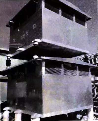
Figure 2 Resistors with metal covers
3.2 Abnormal sound during operation of oil-filled current transformers
Current transformers in operation will cause abnormal sound when overloaded, open circuited in the secondary circuit, discharge due to insulation damage, or suspended potential discharge due to poor contact of the end screen. Local corona caused by uneven application of semiconductor paint and loose bolts clamping the core will also cause loud noises. If abnormal sound occurs, the cause of the abnormal sound should be correctly determined and the correct treatment method should be taken in time. Careful observation should be made and the cause of the abnormal sound should be determined by instrument indications. If it is caused by overload, the load should be reduced to below the rated value and its operation should be observed. If it is caused by the secondary circuit, the operation should be stopped immediately (or the load should be reduced to a minimum), and necessary safety measures should be taken during the handling process to prevent electric shock. If the discharge is caused by insulation damage, it should be replaced. If the suspended potential discharge is caused by poor contact of the end screen, the current transformer needs to be powered off and the end screen contact connection should be tightened.
3.3 The oil level of the oil-filled current transformer is low
Generally, the operation and maintenance personnel will consider the oil level to be normal as long as they see the oil level scale. When the oil level of the current transformer is low, they should first observe whether there is oil leakage on the ground and around the transformer. Secondly, use an infrared thermometer to detect whether the current transformer body and iron core with low oil level are overheated (if there is no power outage plan for maintenance in a short time, the infrared temperature measurement cycle should be shortened and follow-up testing should be strengthened). Finally, check whether the secondary circuit current of related protection devices and instruments is normal. If any or several of the above inspection items are abnormal, the filter should be replaced in time to repair the transformer. Similar to the low oil level and overheating problems in common capacitor failures, timely detection and maintenance are the key to avoiding equipment damage.
3.4 Silicone rubber cracking of silicone rubber transformers
As shown in Figure 3, 35kV silicone rubber current transformers are often used in domestic converter station filters and shunt capacitor devices in the early stage. This type of transformer is prone to cracking defects of primary lead silicone rubber during long-term operation. Since the filter field equipment has a fence during operation, the cracking position of the primary lead cannot be found through inspection. If it is not found, it is easy to reduce the primary insulation capacity and cause protection misoperation. Therefore, the annual routine maintenance of the converter station should focus on checking the silicone rubber current transformers that have cracks and cracking trends. Generally, when this problem occurs, the repair method is adopted when the insulation is good after the test verification. After the treatment is completed, the test verification is carried out again. It is qualified only when it meets the test requirements. Similar to the insulation damage in common capacitor failures, regular inspection and repair are effective means to prevent faults.
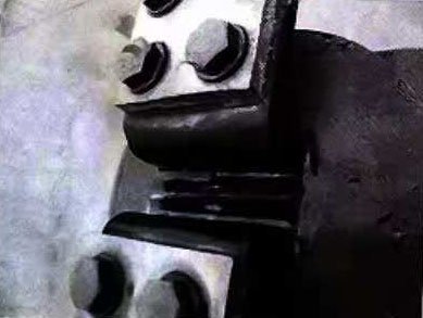
Figure 3 Silicone rubber cracking at the primary lead outlet
4.Analysis of common capacitor failuresof lightning arrester
As a common overvoltage protection device in both DC converter stations and ordinary AC substations, this section mainly analyzes the defects that are more likely to occur in lightning arresters in AC and DC filters of DC converter stations.
Due to the low voltage level of the lightning arrester in the AC filter, it is usually not easy to have problems. The most common failure of the lightning arrester body is that the insulation of the lightning arrester is damp, resulting in insulation damage of the lightning arrester. In this case, the lightning arrester can only be replaced.
Due to its particularity, the DC filter lightning arrester may cause insulation breakdown of the lightning arrester and short circuit to the ground in certain operating modes or certain fault conditions of certain DC systems, and the lightning arrester needs to be replaced as a whole. Similar to the insulation damage problem in common capacitor failures, the insulation of the lightning arrester is also one of the common failures. Timely detection and replacement are the key to ensuring the safe operation of the equipment.
