Casting and rolling is to guide the molten aluminum liquid into the gap between the two casting rolls through the distributor and the casting nozzle. Water is passed through the casting roll, and the two rolling rolls rotate at the same speed but in opposite directions. The aluminum liquid cools in the gap, crystallizes and solidifies, deforms, and forms a strip, which undergoes a series of complex physical and chemical changes. This process is completed in just a few seconds, and there are many disciplines involved, including heat transfer, viscous fluid mechanics, tribology, and rolling plastic deformation theory. Many problems have not been fully clarified in theory, so it is difficult to fully grasp them in production practice. For the production of capacitor aluminum foil, the stability of the casting and rolling process directly affects the dielectric properties and mechanical properties of the final product. Enterprises must have a deep understanding of the problems that may occur in the narrow space of the roll gap within a few seconds, such as uneven heat transfer, crystallization defects or surface oxidation. These factors may lead to an increase in the pinhole rate, uneven thickness or insufficient tensile strength of the capacitor aluminum foil, which is the core topic of optimizing the casting and rolling process.
The basic forms of casting and rolling are as follows:
Bottom injection type – two rollers are arranged horizontally, aluminum liquid is injected from the bottom, and the strip is discharged from the top (see Figure 1). The products produced by this method have dense organization and good quality, but the operation is troublesome, and few people use it now. This method was once used in the production of capacitor aluminum foil.
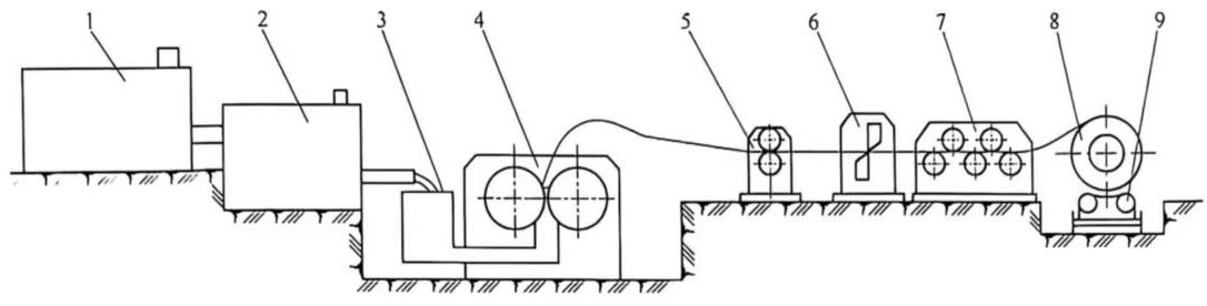
Figure 1 Schematic diagram of bottom injection casting and rolling machine
1- Melting furnace; 2- Static furnace; 3- Front box; 4- Casting and rolling machine; 5- Double traction machine; 6- Shearing machine: 7- Straightening machine: 8- Coiler: 9- Coiler
Inclined type – the center line plane of the two rollers is at an angle of 75° to the ground plane. The aluminum liquid is injected from the side, rises a certain distance along the inclined surface of the casting nozzle, and then flows out of the casting nozzle, enters the casting and rolling area, and discharges the strip from the other side (see Figure 2). The products produced by this method have dense organization. However, it is difficult to stand the plate, and the operator is required to be high, which increases the geometric waste when standing the plate, affecting the yield rate.
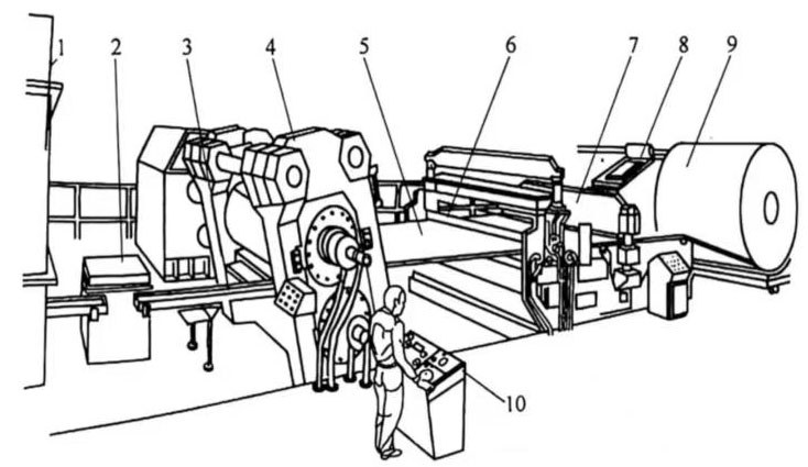
Figure 2 Schematic diagram of inclined casting and rolling mill
1-Stationary furnace; 2-Front box; 3-Flow trough; 4-Casting and rolling mill; 5-Casting and rolling strip; 6-Double traction machine; 7-Shearing machine; 8-Coiling machine; 9-Casting and rolling strip; 10-Operating table
Horizontal type-the center line plane of the two rollers is perpendicular to the ground plane, the aluminum liquid is injected from one side, and the outlet plate surface is parallel to the ground plane (see Figure 3). It is easy to operate, it is easier to stand the plate, no geometric waste is generated when standing the plate, and the yield rate is higher, but the organization is not as dense as the former.
For the production of high-quality double zero aluminum foil, the bottom injection type should be the best for casting and rolling billets, and the inclined type is second. This method was once used in the production of capacitor aluminum foil.
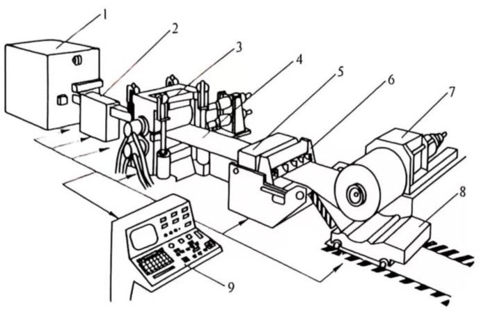
Figure 3 Schematic diagram of horizontal casting and rolling mill
1-Stationary furnace; 2-Front box; 3-Casting and rolling mill: 4-Casting and rolling strip; 5-Double traction machine; 6-Shearing machine; 7-Coiling machine; 8-Rolling trolley; 9-Operating table
1 Casting parameters of capacitor aluminum foil
The main parameters of capacitor aluminum foil casting and rolling are:
(1) Casting and rolling zone length L0 The distance between the aluminum liquid flowing out of the casting nozzle and the aluminum strip leaving the center line plane of the two rollers is collectively referred to as the casting and rolling zone. The casting and rolling zone is subdivided into three parts, namely:
Cooling zone L1-the distance between the aluminum liquid leaving the casting nozzle and the start of crystallization when it contacts the roller surface. The size of this interval is related to the liquid level height of the front box, the cooling intensity of the rollers and the gap between the nozzle and the roller.
Casting zone L2 (also called crystallization zone)-the distance between the start of crystallization when it contacts the roller surface and the completion of crystallization. The size of this interval is related to the casting and rolling temperature, casting and rolling speed, and cooling intensity.
Rolling zone L3 (also called deformation zone)-from the completion of crystallization to leaving the center plane line of the rolling. Its size is determined by the casting and rolling temperature, casting and rolling speed, roller diameter and strip billet reduction.
The schematic diagram of the casting and rolling zone length is shown in Figure 4.
(2) Casting and rolling temperature, strictly speaking, it should be the temperature in the casting and rolling zone. However, along the direction of the strip forward, the temperature of each point in the casting and rolling zone is different, and it is difficult to measure accurately. In order to facilitate production, measurement and mastering, the aluminum liquid temperature in the front box of the casting and rolling is regarded as the casting and rolling temperature.
(3) Casting and rolling speed refers to the speed of the cast and rolling strip when it leaves the roll, including the forward slip value.
(4) The height of the front box liquid level refers to the height difference between the front box liquid level and the liquid level at the front of the casting nozzle.
(5) Cooling intensity, strictly speaking, should be the heat taken away from the casting and rolling zone by the cooling water in the casting and rolling roller sleeve and the surrounding environment per unit time during the casting and rolling process. However, this issue is very complicated and difficult to measure. Therefore, it is usually referred to as the temperature difference between the inlet and outlet cooling water during production.
(6) Coiling tension refers to the tension applied by the coiler to the strip.
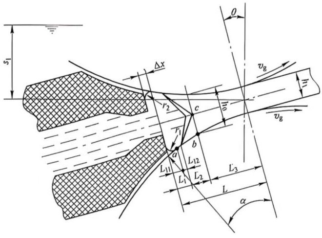
Figure 4 Schematic diagram of the length division of the casting and rolling zone
2 Calculation of the casting and rolling zone
As mentioned above, the casting and rolling zone is divided into three zones, represented by L1, L2, and L3, respectively. European and American countries mainly consider factors such as the surface tension of the metal oxide film, the density of the metal solution, the height of the front box liquid level, the height difference of the feed nozzle, the billet discharge speed, the solidification speed of the cast and rolled billet and the radius of the roller, and put forward the following calculation formula:
![]() (1)
(1)
Where Py-metal solution density;
σbz-surface tension coefficient;
g-gravitational acceleration;
S1-height difference between the front box liquid level and the feed nozzle;
ν1-bill discharge speed;
h1-slab outlet thickness;
∆h-absolute reduction;
νng-average solidification speed of the cast and rolled billet, “(h,+ Ah)2t
tng-casting solidification time;
R-casting mill roll radius.
In recent years, my country’s scientific and technological workers have made unremitting research and exploration on casting and rolling theory. They not only consider the surface tension of the metal film in the calculation of L1, but also consider the overheating problem of the metal, and make supplementary corrections to it: they also put forward their own calculation formula for the inclined crystallization zone L2. The calculation formula for the full casting and rolling zone of capacitor aluminum foil is as follows:
![]() (2)
(2)
Where:
 (3)
(3)
Where k-solidification coefficient;
D-casting roll diameter:
L-total length of casting and rolling zone.
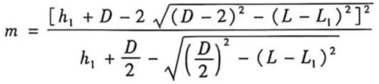
According to the geometric relationship between the casting and rolling roll gap and the casting and rolling nozzle during assembly, Professor Sun Binyu established the calculation formula for the total length L of the casting and rolling zone:
![]() (4)
(4)
Where:
 (5)
(5)
∆x is the forward extension of the lower nozzle fan, mm.
The geometric relationship of the casting and rolling zone is shown in Figure 5. The total length of the casting and rolling zone is related to the thickness, gap value, diameter and forward extension of the lower nozzle fan of the casting nozzle.
Figure 5 Geometric relationship of the casting and rolling zone