1.Importance of equipment installation tracking
In DC converter stations, shunt capacitors, as one of the key equipment, play an important role in the stable operation of regional power grid interconnection and high-power power transmission. DC converter stations usually shoulder the important tasks of regional power grid interconnection and high-power power transmission. The safe and stable operation of a single station often determines the safe and stable operation of the large power grid system, and the safe and stable operation of each device becomes the cornerstone of the safe and stable operation of the converter station. China, as the country with the largest number of DC converter stations in operation and the richest operating experience in the world, has accumulated a lot of converter station operation and maintenance experience. Years of operating experience of DC converter stations have shown that the tracking and control of operation and maintenance personnel during the equipment installation process can effectively reduce the number of defects and hidden dangers after the equipment is put into operation to a considerable extent, and ensure the safe and stable operation of the equipment for a considerable period of time.
The equipment of ordinary AC substations is all included in DC converter stations. At the same time, converter stations also have equipment that AC substations do not have (converter valves, DC field equipment, water cooling system equipment, AC and DC filters and shunt capacitors equipment, etc.). The technical content and structural complexity of these equipment are much more complex than those of ordinary AC substation equipment, which determines the complexity of its equipment installation, construction and commissioning process. Tracking the equipment installation process can directly integrate the various experiences accumulated in the daily operation and maintenance of the converter station into the equipment installation process, eliminate incorrect, unreasonable, and non-standard installation methods and installation problems found on site in the bud, and ensure the health level of the equipment after commissioning.
The complexity and importance of DC equipment also determine that it cannot only focus on result acceptance, surface acceptance, and functional acceptance like ordinary substations. The operation and maintenance personnel of the DC converter station should track and accept the entire process from the equipment civil foundation, equipment factory test, equipment entry, unpacking, installation, on-site handover test, and commissioning. In particular, it is necessary to strengthen the tracking and acceptance of hidden projects to eliminate various hidden dangers in the infrastructure stage to the greatest extent. The construction of DC converter stations is a heavy task and time-sensitive. It is particularly necessary for converter station operation and maintenance personnel to strengthen the tracking of equipment installation. Equipment operation and maintenance personnel are more likely to discover and solve problems with a sense of responsibility as the owner, which further guarantees the quality of equipment installation. At the same time, the installation tracking of DC converter station equipment can in turn cultivate DC converter station operation and maintenance professionals, so that tracking personnel can better understand and master all kinds of equipment knowledge.
Tracking of equipment installation process is crucial for DC converter station operation and maintenance and talent training. At present, the State Grid Corporation system converter station has initially formed a relatively complete method system for equipment installation tracking. Through the preparation of tracking, acceptance work instructions, equipment infrastructure installation and commissioning daily reports and other operational documents and summaries, the operation and maintenance personnel are guided to learn equipment installation.
2.AC and DC filter and shunt capacitors device installation tracking content
The installation tracking content of AC and DC filters and shunt capacitors devices mainly has 5 stages (of course, this is also the stage process of most equipment tracking): ① Tracking of civil construction foundation; ② Tracking after the equipment arrives; ③ Tracking of equipment installation process; ④ Tracking of equipment commissioning and testing; ⑤ Acceptance after the equipment construction is completed. The following five aspects are used to describe the installation tracking content and precautions of AC and DC filters and shunt capacitors.
2.1 Tracking of civil engineering construction
The tracking of civil engineering construction is usually considered a “chicken rib” project in the eyes of many substation and converter station operation and maintenance personnel. The tracking and acceptance are not taken seriously, which leads to many problems. For example, the ground treatment is not up to standard, resulting in the collapse and settlement of the ground around the equipment foundation after 1 to 2 years of operation, which seriously threatens the safe and stable operation of the equipment. A domestic converter station once had a hidden fault of the TA secondary cable pipe and TA junction box seriously separated due to the collapse of the foundation around the AC filter high-voltage TA (current transformer), as shown in Figure 1 and Figure 2. The operator had to apply for the suspension of the filter group for disposal to prevent the serious consequences of the mother differential action caused by the failure of the filter TA circuit. This situation is particularly aimed at the foundation with collapsible loess structure in some areas of the northwest. If it is not handled properly during the infrastructure stage or later maintenance, it is easy to cause this problem.
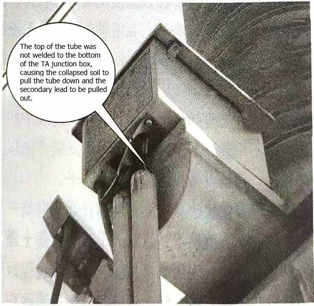
Figure 1 Schematic diagram of the junction box of the TA pipe sinking

Figure 2 Schematic diagram of the bottom of the pipe sinking
Of course, to solve this problem, on the one hand, we require the construction unit to work hard on the foundation treatment during the infrastructure construction phase to keep the soil around the foundation stable (3/7 of the gray soil can be compacted to a certain thickness or the opinions of the relevant design parties can be sought) to prevent collapse and sinking; on the other hand, the method shown in Figure 3 can be used on the upper and lower parts of the pipe, the upper pipe is welded to the fixed position at the bottom of the TA to prevent the pipe from sinking, and the lower part uses a plate with an “L”-shaped cross-section to support the pipe to prevent sinking. In general, during the infrastructure stage, the TA manufacturer or the construction party is required to weld the upper pipe to the fixed position at the bottom of the TA. If this method is used, the empty pipe is still pulled down, and the bottom support method can only be further adopted to prevent sinking. Ensuring the safe operation of key equipment such as shunt capacitors on a stable foundation is the guarantee for the overall safe and stable operation of the converter station.

Figure 3 Schematic diagram of TA pipe penetration sinking treatment
In addition, if the treatment around the equipment foundation is not up to standard, it may also cause the equipment to tilt, causing the insulator to break under lateral tension and causing equipment accidents.
Tracking of civil foundation construction is often the first step in equipment on-site tracking. Based on experience, the tracking is mainly focused on the following aspects.
(1) Tracking of civil construction around the equipment foundation. Whether the backfill soil around the equipment concrete foundation is carried out in accordance with the process required by the civil construction drawings, such as: the compaction thickness of the lime soil (lime and clay mixed in a certain proportion), the thickness of the gravel layer, the thickness of the concrete surface layer, whether there are horizontal or tilt requirements on the ground, etc. All these require our tracking personnel to be familiar with the drawings first, and then go to the site to track in a targeted manner. In this way, we can learn something and become familiar with the site. As shown in Figure 4, the backfill soil treatment around the concrete foundation is not up to standard, resulting in ground settlement, which in turn threatens the safe and stable operation of equipment including shunt capacitors.

Figure 4 Settlement around equipment foundation
(2) Tracking of equipment foundation civil construction. The so-called equipment foundation usually refers to the concrete structure on which the equipment body is installed. The concrete structure is embedded to a certain depth below the ground to ensure that the equipment above the ground is firm and stable. This part of the tracking should check whether the construction party has carried out the construction of the structure according to the requirements of the drawings, and whether the shape of the structure, the construction depth, and the maintenance of the concrete after construction (especially in the cold winter environment) meet the requirements. Otherwise, it will seriously affect the quality of the concrete.
(3) Grounding grid construction. In civil construction, the grounding grid construction should pay special attention to the process acceptance. After the construction unit completes the laying and welding of the grounding grid, due to the next step of construction, it is generally necessary to backfill the earth quickly. Before backfilling the earth, the construction party will generally notify the supervision and operation unit tracking personnel to take photos for acceptance. This acceptance process is usually called hidden project acceptance in engineering. Since the grounding grid will be used as a safe grounding, protective grounding, signal grounding, etc. for various equipment in the future, and also as a discharge channel for various fault currents, it also plays an important role in the operation of the entire substation. The grounding grid acceptance should pay attention to whether the material, shape, etc. used in the grounding grid meet the requirements of the regulations (design drawings), and whether the welding process meets the welding quality requirements. After the tracking personnel take photos and keep them, they should be filed and organized in time, and archived as the basic data for substation construction in the future.
(4) Cable trench construction and filter field drainage facility construction. On-site tracking personnel track whether the cable trench construction meets the design requirements. In addition, they should also pay attention to whether the trench firewall layout meets the standard requirements (familiarize yourself with the standards before tracking), whether there are drainage holes in the cable trench, etc. If the cable trench is not drained smoothly, it is very likely to cause a large amount of water in the trench to be unable to be discharged after raining as shown in Figure 5. In severe cases, it may cause cable damage, DC grounding, and protection malfunction. The filter field is usually located on a large area of hardened concrete ground. It should be noted that the drainage facilities on the ground are constructed according to the requirements and whether the concrete ground has any inclination requirements. If it rains during the construction process, this is the best opportunity to check whether the drainage of the large area of concrete construction ground is smooth and whether the drainage wells and rainwater wells are functioning normally. At this time, personnel should be organized to inspect the large area of concrete ground, drainage wells, and rainwater wells, and urge the construction unit to deal with serious problems in a timely manner. During the inspection of underground drainage wells, attention should be paid to whether the well walls and underground parts are well constructed. Otherwise, long-term operation may cause the well walls to collapse, soil to enter the well, and the drainage pipes to be blocked (usually the construction quality of this part is poor and it is not easy to attract the attention of all parties), as shown in Figures 6 and 7.
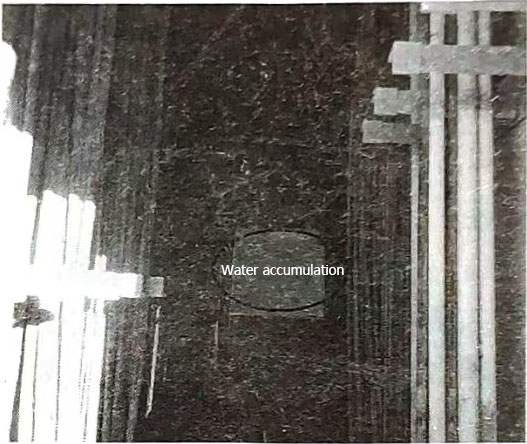
Figure 5 Water accumulation in the cable trench
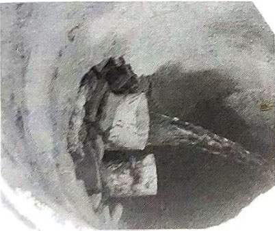
Figure 6 Drainage well with poor wall construction technology
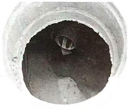
Figure 7 Drainage well with blockage at the bottom of the well
(5) Methods for solving problems during tracking. During the civil engineering tracking process, if the construction party fails to construct according to the design drawings or does not meet national standards, design specifications (such as the installation standards of shunt capacitors) and relevant enterprise standards, or if more serious hidden dangers and defects are found, the tracking personnel should take photos and record them, and issue a project contact form to the supervisor, construction party or design institute, requiring rectification within a time limit. The use of the project contact form is applicable to all tracking occasions, and the communication records of these contact forms with infrastructure units and equipment manufacturers should be archived as engineering infrastructure materials.
2.2 Tracking after the arrival of the filter equipment
After the filter equipment arrives and before unpacking, the supervisor and the operation and maintenance unit will generally be notified to come to the site for witnessing, and there will usually be personnel from the equipment manufacturer on site. At this time, the following points should be noted:
(1) Check whether the external packaging of various filter equipment (shunt capacitors, resistors, reactors, mutual inductors, lightning arresters, etc.) is damaged. Pay attention to whether the equipment with damaged external packaging is intact and conduct a careful inspection. Minor damage that may cause long-term operation hazards of the equipment (not considered by the construction party or manufacturer to constitute damage) should be boldly raised and photographed for preservation. If necessary, an engineering construction contact form should be issued, or all parties should be organized to discuss until a clear reply is given.
(2) Pay attention to the collection of equipment certificates, factory manuals, test reports, etc., or the construction unit should collect them and hand them over as data later, but the tracking personnel should keep a record of the data to ensure the integrity of the future data handover.
(3) Pay attention to the collection and collation of basic equipment information to prepare for the compilation of substation operation procedures, maintenance and test procedures, and equipment ledgers. The data collected by photography or recording mainly include: ① Nameplates of capacitors, reactors, resistors, lightning arresters, and transformers, which should correspond to the equipment (there are usually multiple types of capacitors, reactors, resistors, transformers, lightning arresters, etc. in a group of filters); ② Schematic diagram of capacitor tower grouping: Usually, before the capacitor leaves the factory, the capacitor tower bridge arm has been balanced according to its actual capacitance value, so the position of each capacitor on the tower has been fixed, and the construction party only needs to install and wire according to the grouping diagram. While paying attention to collecting the above equipment parameters, special reminders should also be paid to collecting information on insulators in the filter field, mainly including model, design creepage distance, etc., to accumulate data for future equipment anti-pollution flashover related work.
(4) After the capacitor equipment arrives at the site, in order to ensure product quality, batch sampling tests should generally be carried out, and at least one capacitor unit of each type in each batch should be carried out. A batch refers to all products that are oiled at the same time. When the number of a certain capacitor in a batch of products exceeds 50 units, the sampling rate should not be less than 2%. If any capacitor fails any test, the construction unit has the right to reject all capacitors in the batch. During this process, the operation and maintenance personnel should supervise the construction unit to carry out this work to prevent capacitors with batch problems from being put on the tower, which will leave long-term hidden dangers for the operation of the equipment.
2.3 Tracking of filter equipment installation process
Installation of capacitor tower: During the installation of capacitor tower, the construction unit should be supervised from time to time to install according to the equipment number of the capacitor equipment when it leaves the factory. It is usually hoisted layer by layer. After the hoisting is completed, the upper layer of supporting insulators is installed (or the upper layer of insulators is directly installed on the capacitor layer to be hoisted, and hoisted together, as shown in Figure 8).
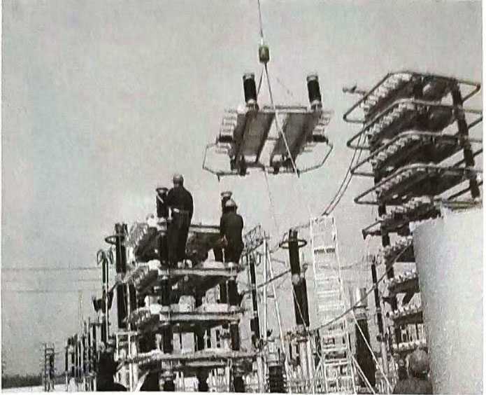
Figure 8 Hoisting operation of capacitor tower layer
During the installation, the construction unit should also be reminded to pay attention to the protection of finished products. The capacitor porcelain bushing should not be stressed to avoid hidden oil leakage defects, which cannot be exposed in a short time. After commissioning, the capacitor will cause oil leakage under the action of thermal effect. At the same time, the supporting insulators should be prevented from being stepped on and damaged by tools. It is strictly forbidden for personnel to pass tools by “throwing” up and down during construction. When connecting the wires between capacitors, tighten the connections according to the torque requirements (currently, the more common capacitor joint connection uses M16 nuts, as shown in Figure 9, and the tightening torque is generally 20NM) to prevent the joints from loosening and heating or over-tightening, which may cause oil leakage after the joints are put into operation (equipment manufacturers will configure torque wrenches with appropriate torques when leaving the factory, and usually configure special tools and instruments with the equipment, which are proposed by the operation and maintenance unit during the review stage of the equipment bidding and procurement technical specifications, or some manufacturers configure them specifically for users).
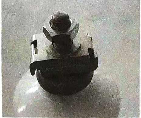
Figure 9 Connection diagram of capacitor joint wire clamps, screws and nuts
Installation of other equipment: mainly including the installation of resistors, reactors, lightning arresters, and TAs in the filter field. In addition to urging the construction unit to pay attention to the protection of finished products during the installation process, the following points should also be noted: ① The bolts and nuts used to fix the resistors and reactors should be non-ferromagnetic stainless steel bolts and nuts (hot-dip galvanized materials can be used for wire clamp connections); ② If the TA in the filter field is an oil-filled TA, special attention should be paid to the good protection of the end screen and the reliable connection. Timely restoration should be paid after the test; ③ All kinds of wire connections should prevent the wires from causing stress on the equipment; ④ There should be drainage holes at the bottom of some crimping hardware connections. Figures 10 to 13 are the on-site installation photos of the type reactor, resistor, oil-filled TA, and lightning arrester.
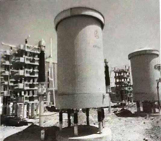
Figure 10 On-site installation photo of dry-type reactor
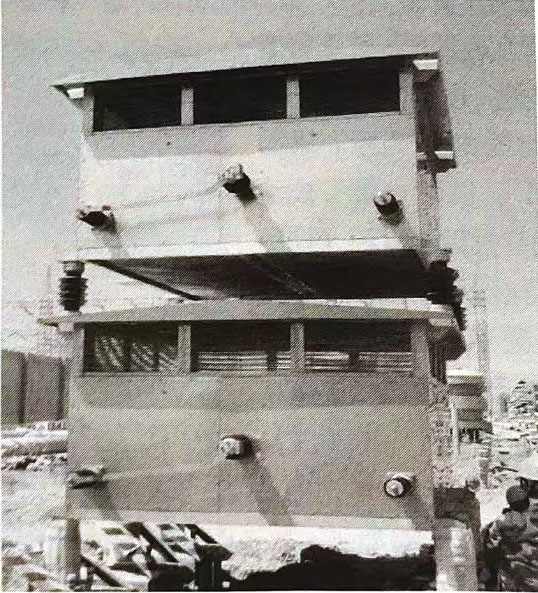
Figure 11 On-site installation photo of resistor
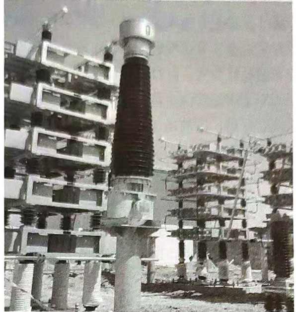
Figure 12 On-site installation photo of oil-filled TA
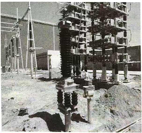
Figure 13 On-site installation photo of lightning arrester in filter field
2.4 On-site commissioning and test tracking of filter equipment
On-site commissioning and test tracking of filter equipment are generally rarely used after the equipment is put into operation (unless tuning test is required after replacing the inductor component), but as on-site operation and maintenance tracking personnel, they should be familiar with the most basic commissioning knowledge, including commissioning purpose and commissioning methods.Correct parameter setting and verification of shunt capacitors during commissioning are also key steps to ensure the normal operation of the filter system.
A set of AC and DC filters must go through a series of calculations, verifications, and commissioning from design to before and after delivery to play its filtering role in the DC transmission system. The first two phases are generally in the design and manufacturing stages, and to play a more ideal role, they must go through on-site commissioning. Debugging of the filter: First, ensure the safe operation of the system. After debugging, the tuning indicators and other indicators meet the design requirements to avoid the input of the filter causing the resonance surface between the system and the filter to amplify the incoming wave current. In addition, the overvoltage generated when the filter is put into operation should be limited to a limited range so as not to damage other equipment. Second, ensure the safe operation of the filter itself. After the filter is debugged and put into operation, the harmonic current flowing into the filter will not cause the capacitor, inductor, and resistor of the filter to be overloaded, and the overvoltage and overcurrent when the filter is switched on will not cause damage to the components of the filter body. These measures ensure that the filter and its shunt capacitors operate stably and reliably in the system.
Inspection before debugging (Tongtang said cold debugging): After all the filter equipment is installed, a detailed installation inspection is performed on all the equipment to ensure that the wiring of each device is correct. The general principle of debugging is to change the reactance value by adjusting the distance between the upper and lower coils of the reactor so that it resonates with the capacitor at the debugging frequency, thus completing the debugging before the filter is put into operation.
Debugging method: There are three methods for debugging filters: amplitude-frequency characteristic method, discharge oscillation method, and phase-frequency characteristic method. The first two methods have large errors, and the phase-frequency characteristic method is more commonly used in practice. Input the resistor voltage and the total voltage of the filter into the two channels of the same filter respectively, and compare the phase angles to determine whether the filter is resonant. Usually, the two voltages are input into different axes (coaxial input has large errors and is not conducive to accurate tuning). When observing the changes in the two phases, the graph changes from an ellipse to a straight line, and the resonance can be determined. This is easy to observe and has high accuracy.
The main process of debugging using the phase-frequency characteristic method:
(1) Connect the wires according to the measurement requirements.
(2) Place a thermometer on site for temperature measurement.
(3) Calculate the tuning frequency under the current situation, whether the tuning frequency of the filter is positive or negative, and what the deviation value is (positive and negative can be determined based on the system impedance).
(4) Turn on the power supply and adjust the oscilloscope for observation.
(5) Adjust the display of the frequency meter and the power supply frequency of the signal generator (which should be the tuning frequency).
(6) Adjust the input voltage of the signal generator so that the oscilloscope graph is easy to observe and not distorted, which is convenient for improving accuracy.
(7) Adjust the distance between the upper and lower coils of the filter reactor (actually change the mutual inductance of the reactor) and change its reactance value until the oscilloscope graph changes from an ellipse to a straight line.
However, the actual change in the inductance value of the reactor is not a continuous adjustment (that is, the distance between the upper and lower coils is graded), so the oscilloscope graph can only be the most approximate straight line during the actual debugging process.
The above method can be used for cold tuning of high-pass filters and double-tuned filters, so this method is more practical in engineering. After the filter is debugged by this method, the filter can meet the design requirements and be put into system operation safely and reliably.
Before debugging and testing the filter, the tracking personnel need to be familiar with the debugging method in advance, master the test steps during the debugging process, and focus on learning debugging wiring and instrument operation during the debugging period.
2.5 Acceptance of filter equipment after construction
(1) The following general requirements should be noted for the acceptance of filters and shunt capacitors equipment (including DC filters):
1) First, the construction unit should complete the construction, organize the personnel of the unit to conduct self-acceptance, keep the self-acceptance records, and submit to the supervision unit that the conditions for acceptance are met after the self-acceptance is passed.
2) After receiving the notice from the construction unit that the self-acceptance is completed and requesting it to organize the acceptance, the supervision unit will start to organize the acceptance. The acceptance must be organized by the on-site supervision unit, and the construction unit, operation and maintenance unit personnel, design unit and even manufacturer personnel will be organized to participate.
3) List the problems found during the acceptance one by one, preferably with photos, and provide timely feedback for rectification.
4) If there are many problems of the same type or obvious construction quality problems, the acceptance can be stopped. Due to many problems and low-level construction quality problems, the operation and maintenance unit may consider that the conditions for acceptance are not met and require the construction unit to rectify them as soon as possible before re-accepting according to the acceptance process.
5) After the acceptance is completed, the signing procedures of all parties concerned should be completed at the same time. The operation and maintenance unit can completely lock the fence door of the filter equipment at this time, and any personnel are strictly prohibited from entering the equipment area without authorization.
(2) Acceptance content:
1) Appearance inspection.
There should be no residue on the filter and shunt capacitors device (capacitor tower, resistor inside and outside, reactor inside and outside, transformer, lightning arrester, etc.), and they should be clean. The capacitor tower and other primary wiring should be correct, and the wiring connection terminals should not be loose (the nuts of the capacitor connector M16 should be checked according to the torque of 20NM). The grounding point of the equipment should be firm and clearly marked. The insulators of each equipment, the porcelain bushings of capacitors, current transformers, and lightning arresters should be clean, without cracks or damage, and there should be no signs of oil leakage at all joints and welds of capacitors. The nuts, flat washers and spring washers for connecting the lead wires of the capacitor bushing should be complete. The capacitor shell should not be bulging, deformed, rusted, etc.
The capacitor frame should be kept in a horizontal position, the support insulators should be vertical to the ground, firmly fixed, and the paint should be intact. The capacitor should be installed with its nameplate facing the side of the channel and numbered in sequence. The connection wires of the capacitor terminals should meet the design requirements, the wiring should be symmetrical, neat and beautiful, and the busbars and branch lines should be marked with phase colors. The shell of the capacitor insulated from the ground on each layer of the capacitor tower should be connected to a fixed potential.
Current transformer: The porcelain sleeve has no cracks or damage, the junction box is well sealed, the secondary lead is not stressed at the pipe penetration, and the plugging is good; the end screen is reliably grounded; the oil level of the oil-filled TA is indicated at 1/3 to 3/4. For silicone rubber transformers, the main attention should be paid to the good sealing of the junction box, and the silicone rubber of the primary lead should be well sealed and crack-free.
Appearance inspection of the reactor: The insulation of the pillars and coils should be free of damage and cracks: the coil is not deformed; the pillar insulators and their accessories are complete. All exposed parts of the reactor should have a good anti-corrosion layer and meet the painting requirements of outdoor anti-corrosion electrical products. The inside of the coil is clean and free of debris, and the reactor air duct should be clean and free of any debris. In addition, special attention should be paid to the fact that the fixing bolts (nuts) on the reactor body and the bottom bracket should be stainless steel (non-magnetic) parts, and galvanized materials should not be used to prevent heat during operation.
All the above-mentioned filter (or shunt capacitors) equipment connection bolts tightening in the fence (except for capacitors connected with wire clamps or materials that clearly cannot be checked according to the standard torque) must be checked with a torque wrench with the corresponding torque to prevent the equipment joints from heating up after commissioning. The tightening torque of the bolts refers to the equipment connection bolt control torque table in Appendix A. It should be pointed out that the bolts tightened in accordance with Appendix A generally refer to the bolts that use the galvanizing process (this process method is used to manufacture bolts in most cases in substations) and the strength grade is clearly marked on the bolts. Bolts of other materials can only be implemented as a reference. For example: there are a considerable number of stainless steel bolts (such as A2-70 material) in the filter field, and in general, the tightening torque of stainless steel bolts of the same diameter commonly used in substations is implemented with reference to the tightening torque of 4.6-grade galvanized bolts.
2) Equipment acceptance test in the device. Before the filter and shunt capacitors device are put into operation, the construction unit shall conduct acceptance tests on all equipment in the filter and shunt capacitors in accordance with GB50150-2006 “Electrical Equipment Installation Engineering Electrical Equipment Acceptance Test Standard”. The acceptance test must be qualified, and the test data will be archived and used as the basis for various evaluations and maintenance of the equipment in the future (because when the test score of the equipment status quantity test is performed, the acceptance test data is generally used as the initial data of the equipment). In order to ensure the capacitance balance between the capacitor tower bridge arms of the DC converter station filter and shunt capacitors, an unbalanced current test is generally required to ensure that the unbalance meets the requirements.
3) Acceptance of relay protection devices. The filter and shunt capacitors device will be equipped with large group filter protection and small group filter protection, and the DC filter will be equipped with a DC filter protection device. Before the conditions for commissioning are met, the protection device must also be accepted at the same time. The various indication checks of the protection device, the set value check of the protection device, and the protection transmission record check of the construction unit should all be completed and correct. The specific contents of other acceptance of filter and shunt capacitors protection devices are the same as those of various protection devices in ordinary AC substations. They can be implemented by referring to relevant regulations. This book will not elaborate on them.
4) Materials to be submitted for equipment acceptance. When accepting filter and shunt capacitors devices, the construction unit shall submit the following materials and documents: various equipment product manuals, factory test records, qualification certificates and installation drawings provided by the manufacturer; on-site adjustment test records of the construction unit; various technical documents, meeting minutes, notice rectification orders, etc. that occurred during the construction process; design data files, design change notices, etc.
