How car capacitor work in cars?
1.Turn on the turn signal switch, the series coil 3 is energized, and the current flow is formed by the battery positive pole – series coil 3-contact 1-turn light switch – turn signal and turn indicator – ground – battery negative.
At this time, the parallel coil 4 and the capacitor 7 circuits are short-circuited by the contacts, and the series coil 3 generates an electromagnetic force greater than the spring force of the spring piece 2 to open the contacts, so that the turn signals are flashed and dark.
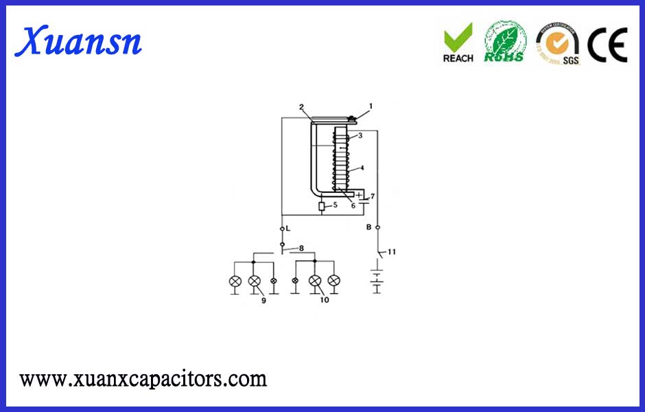
2. After the contact is opened, the power supply charges the capacitor, and the charging current is from the battery positive pole-series coil 3-yoke and iron core-parallel coil 4-capacitor 7-turn light switch-turn signal light and turn indicator light-grounding – The battery negative pole forms a loop.
Since the parallel coil 4 has a large electric resistance and its charging current is small, the turn signal light is still dark. At the same time, since the electromagnetic force generated by the series coil 3 and the parallel coil 4 is the same, the contacts remain open. As the voltage across the capacitor gradually increases, the charging current decreases until the electromagnetic force generated by the coil is insufficient to overcome the spring force of the spring piece 2, and the electric shock is combined.
3. After the contacts are closed, the current through the turn signal light increases and the light becomes brighter. At the same time, the capacitor is discharged through the contact, and its discharge current is from C “+” – parallel coil 4-iron core and yoke-contact 1-C “-“.
Since the direction of the magnetic field generated by the parallel coil 4 and the series coil 3 during discharge is opposite, the electromagnetic force is weakened, so the electric shock remains closed, so that the turn signal lamp and the turn indicator light continue to illuminate, and the discharge coil is gradually reduced as the discharge current is gradually reduced. 4 The magnetic field produced gradually weakens. When the sum of the magnetic force of the two coils is greater than the spring force of the spring piece 1, the electric shock is opened and the light is darkened again. Repeatedly, the interrupting current is supplied to the turn signal, so that the turn signal flashes at a certain frequency.
The R and C parameters of the capacitor charge and discharge circuit determine the flashing frequency of the turn signal. During operation, the R, C parameters do not change much, so the flash frequency of the turn signal is relatively stable. The arc extinguishing resistor 5 in the flasher is connected in parallel with the contact to reduce the spark of the contact
