1.Operation and maintenance after the shunt capacitor tripping
During the operation of the DC system, if the AC filter or shunt capacitor tripping and the stage III directly trips due to a fault, the operator should carry out on-site disposal in an orderly manner according to the following points:
(1) After the faulty filter or shunt capacitor tripping in the background of the monitoring interface, check the operation status of other spare filter groups. The duty officer should immediately arrange personnel to go to the protection relay room to check the unbalanced current of the replacement filter (or shunt capacitor) put into operation, and go to the site to check whether the primary equipment of the replacement filter (or shunt capacitor) is operating well, and notify the dispatch duty personnel of the on-site situation according to the dispatch relationship. Generally, when the DC system is running at full load, the converter station will have 1~2 groups of spare (here, the reactive dark spare capacity provided by the system is not considered for the time being) filters (capacitors). Regardless of whether it is running at full load or not, if the filter or shunt capacitor tripping, the operator must apply to the dispatcher to transfer the primary equipment of the filter (shunt capacitor) to the maintenance state for maintenance.
(2) Filter or shunt capacitor maintenance operation, in turn, the filter or shunt capacitor is switched to cold standby (open the isolating switch between the circuit breaker and busbar, and disconnect the operating power of the isolating switch), switched to maintenance (close the grounding switch, usually to reduce the operation, only close the grounding switch between the circuit breaker and the filter, and disconnect the power supply of the grounding switch motor).
(3) After the maintenance operation is completed, the operator needs to complete the safety measures for the maintenance of the filter or shunt capacitor, which mainly include: ① Use an insulating rod with a grounding wire at one end, wear insulating gloves, and discharge the capacitors one by one; ② Set up a three-phase 35kV grounding wire on the low-voltage side of the high-voltage capacitor tower; ③ Set up a fence at the interval leading to the adjacent live filter or shunt capacitor, and hang a sign with the value “Stop, high voltage danger!”; ④ At the entrance of the fence door of the filter to be repaired, hang a sign with the value “Enter and exit from here!” and “Work here!”. After the safety measures are completed, the operating work permit personnel will lead the maintenance work leader to the site to confirm the safety measures and explain the energized status of the surrounding equipment. Both parties will sign and confirm on the work ticket, and the work will be permitted to start.
2.Maintenance and treatment of equipment after tripping
2.1 Preparation before maintenance
Prepare the relevant tools, work vehicles, and materials before maintenance in accordance with the requirements of the “Standardized Operation Guide for Fault Replacement and Adjustment of Capacitors in XX Converter Station” in Appendix B, and place them on site in a unified and standardized manner. According to the relevant action information of the protection device, the fault phase of the capacitor can be confirmed, and the lifting platform can be slowly moved to the side of the capacitor of the fault phase (it is advisable to measure the capacitance value of the capacitor in a more comfortable posture for the staff), and the working platform is reliably grounded with a grounding wire. Finally, the working platform is supported to ensure that the platform is level. At this point, the preparation work before maintenance is completed.
2.2 Maintenance process
(1) Appearance inspection. When dealing with capacitor failure, you should first stand on the work lifting platform and conduct a visual inspection of all capacitors in the phase to be repaired layer by layer to confirm whether there is oil leakage, casing cracks, or severe bulging capacitors. If the above situation occurs, then conduct a focused capacitance test on the above capacitors. If it is confirmed to be a faulty capacitor, replace it. Usually, this method can only preliminarily find some capacitors with obvious abnormalities. It cannot be assumed that all faulty capacitors can be found by only this inspection. Under normal circumstances, oil leakage capacitors, casing cracks, or severe bulging capacitors found by visual inspection only account for 10% to 20% of all faulty capacitors. Most faulty capacitors still need to rely on capacitance value testing methods to be found.
(2) Capacitance value measurement. For the remaining capacitors that have no abnormalities in the appearance inspection, the capacitance value of the faulty phase capacitors can only be measured one by one. The faulty capacitor is determined by whether the capacitance value exceeds the standard and replaced; for any converter station, the faulty capacitors confirmed by this capacitance value measurement method generally account for 80% to 90% of the total number of faulty capacitors. It can be seen that in order to completely find all the faulty capacitors on the tower arm, it is necessary to measure and screen them one by one. To determine whether the capacitance value of the capacitor exceeds the standard, you should refer to the provisions of the change of the capacitance value of the capacitor exceeding the standard in Q/GDW 496-2010 or the manufacturer’s equipment manual, and make a comprehensive comparison with historical data to determine whether the capacitance value of the capacitor exceeds the standard.
In addition, during the inspection process, if the shunt capacitor tripping to found , special attention should be paid to the status of the capacitor. The shunt capacitor tripping may be caused by capacitor failure or unbalanced system load. Therefore, the parallel capacitor must be checked separately to ensure that no capacitor that may cause system failure is missed, and confirm whether it needs to be replaced based on the capacitance value measurement results.
However, in some special cases, such as the phase capacitor, the unbalanced current exceeds the standard and trips frequently (especially the early domestic capacitors often have similar situations), and each time after replacing a few capacitors, the capacitor fails again after a few days of operation. In response to such situations, in actual work, the capacitor capacitance value fault screening is usually carried out according to more stringent requirements than the specification requirements. For example, the specification stipulates that the initial value deviation of the capacitor is qualified within 5%~10%. In practice, the qualified capacitance value range is narrowed to within ±2% (basically, the fuse of the small capacitance element inside the capacitor cannot exceed 1, because too many fuses are blown, which increases the probability of capacitor failure after the next charging and commissioning). By raising the requirements for the capacitance value of qualified capacitors, the quality of maintenance is improved, ensuring that the equipment will not trip after long-term operation after maintenance. However, it should be noted that the shunt capacitor tripping may be affected by the uneven distribution of capacitor capacitance values. Therefore, when screening capacitors, special attention should be paid to these potential problems.
By raising the capacitance value standard of qualified capacitors, it is ensured that the equipment will not trip after long-term operation after maintenance. However, raising the capacitance value standard of qualified capacitors also increases the number of faulty capacitors to be replaced and the workload, so this is also contradictory. In the actual maintenance process, the capacitance value requirements of filter capacitors are generally followed, and the qualified range of the capacitance value of parallel capacitors can be appropriately expanded. In recent years, with the substantial improvement in the quality of domestic capacitors, the -5%~10% standard can basically guarantee the quality of equipment operation after maintenance.
We have described the test method of capacitor capacitance in the previous chapter. Here we introduce the measurement of capacitors on site. In actual field measurement, we face a series of practical problems: measuring capacitance in the complex electromagnetic environment of the converter station, with running filters or parallel capacitor equipment around; the capacitor is measured on the tower with as little or no wire removal as possible (the author’s on-site maintenance experience believes that less wire removal is more convenient than using a capacitor bridge test, and several comparisons have been made. I hope readers will experience it in maintenance practice); the maintenance platform is raised to the top of the capacitor tower and the induction electrode is strong. A series of unfavorable factors, how to better measure should follow the following principles:
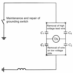
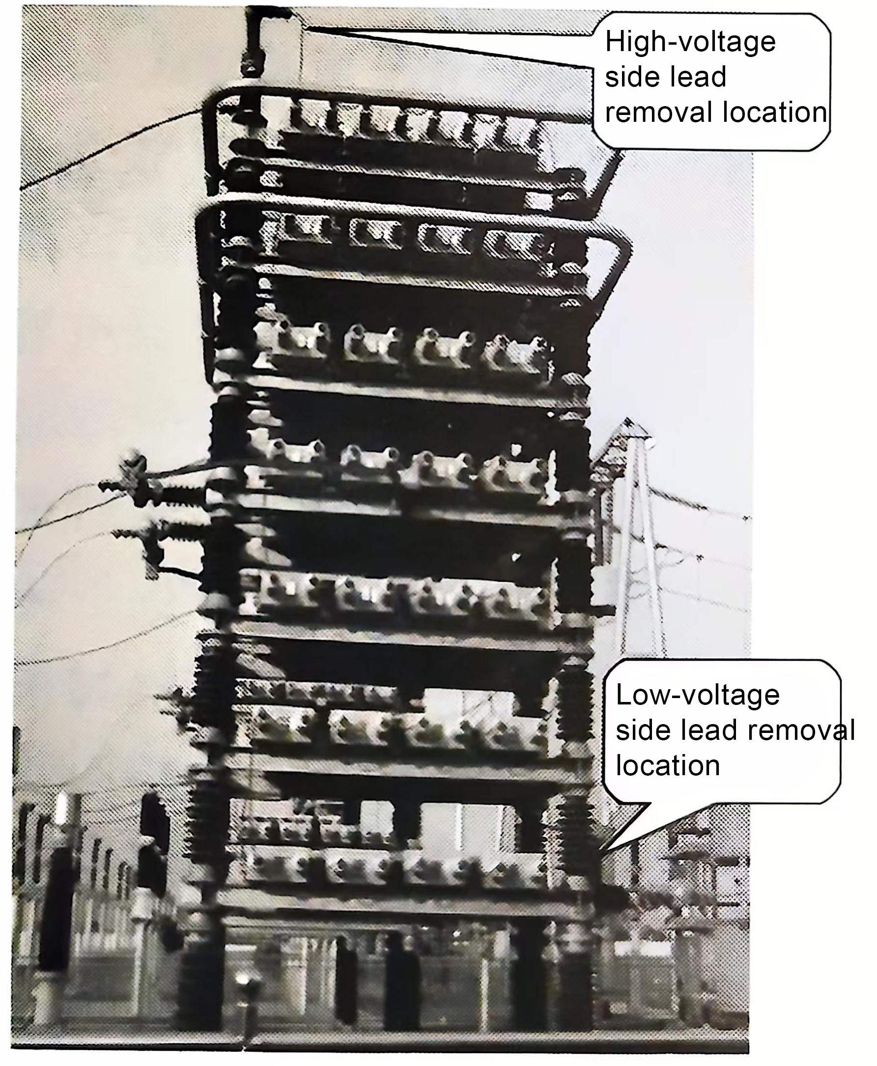
1)Before measuring the capacitance value of the capacitor on the capacitor tower with a capacitance meter, remove the leads connecting the high and low voltage sides of the capacitor tower to other equipment according to the position shown in Figure 1, which cuts off the possibility of generating an induction loop and prevents the electromagnetic field of the DC converter station from generating an induced current in the closed loop, causing the capacitance value data to be unable to be measured. The author’s maintenance practice has proved that as long as the four primary wirings in Figure 1 are removed, the other series and parallel series connection lines do not need to be removed, and the capacitance meter can be used to measure directly. The value is accurate and there will be no electronic capacitance meter data jitter. In this case, the risk of shunt capacitor trippingis avoided. The actual position of the high and low voltage leads of the capacitor tower removed on site is shown in Figure 2.

Figure 1 Schematic diagram of the lead wire removal position

Figure 2 Actual position diagram of the lead wire removal
2) When using the above method to measure the capacitance value, the following issues should be noted: When removing the lead, there will be a strong induced electric “arcing” at the moment the lead is disconnected. Special attention should be paid to prevent arc injury. It is best to wear insulating gloves and goggles when disassembling and restoring the lead; In addition, the removal of the high-voltage side lead is actually equivalent to opening the maintenance safety grounding knife switch (from the perspective of safety supervision and inspection, this is not allowed. It can be protected by adding a temporary ground wire to protect the safety of the personnel performing capacitance testing on the top of the capacitor tower). When testing the capacitance value of the capacitor at the bottom layer, the temporary ground wire should also be removed. There is also induced electricity at the bottom layer, which is smaller than the top layer.
3) When the high-voltage and low-voltage leads are disconnected, the capacitance of the bridge arm of C1, C2, C3, and C4 can also be measured with a capacitance meter.
Using the above method, the capacitance test of all capacitors on the capacitor tower can be successfully completed, and the specific location and number of the faulty capacitors can be obtained. It should be noted that after the faulty capacitor is determined, before the capacitor needs to be replaced, the disconnected leads on the high-voltage and low-voltage sides must be restored (or the high voltage still uses a temporary grounding wire). Otherwise, due to the excessive induction (the maintenance equipment has no maintenance safety measures for grounding), the next step of replacement cannot be performed.
Infrared temperature measurement. During daily operation (before the capacitor trips), infrared temperature measurement of capacitor equipment is also a common method to monitor whether there are potential faults in the running capacitor. This requires us to establish a complete equipment infrared temperature measurement information data ledger, strengthen operation and maintenance management, and control unplanned shutdowns. Through the infrared thermometer, abnormal conditions such as overheating of the capacitor body and loose joints can be detected, and equipment hidden dangers can be discovered early to facilitate the arrangement of planned maintenance and prevent equipment defects from turning into shunt capacitor tripping. DC converter stations will be assessed on the unplanned outage indicators of equipment to avoid outages caused by equipment failure.


