Power supply high frequency filter capacitor selection skills
1) Theoretically, the impedance of an ideal capacitor decreases as the frequency increases (1/jwc), but due to the inductive effect of the pins at both ends of the capacitor, the capacitor should be regarded as an LC series resonant circuit, and the self-resonant frequency is The FSR parameter of the device, which means that when the frequency is greater than the FSR value, the capacitor becomes an inductance. If the capacitor is filtered to the ground, when the frequency exceeds the FSR, the interference suppression will be greatly reduced, so a smaller capacitor is needed in parallel to the ground , Can think about why?
The reason is that small capacitors and large SFR values provide a path to ground for high-frequency signals. Therefore, we often understand in power filter circuits: large capacitors consider low frequencies, and small capacitors consider high frequencies. The fundamental reason is SFR (self-resonance). Frequency) values are different, of course you can also think about why? If you think about it from this perspective, you can understand why the capacitor should be as close to the ground as possible in the power filter.
2) In actual design, we often have questions. How do I know the SFR of the capacitor? Even if I know the SFR value, how do I choose the capacitor value with different SFR value? Should I choose one capacitor or two capacitors?
The SFR value of a capacitor is related to the capacitance value and the pin inductance of the capacitor. Therefore, the SFR value of 0402, 0603, or in-line capacitors with the same capacitance value will not be the same. Of course, there are two ways to obtain the SFR value, 1. ) Device Data sheet, for example, the SFR value of 22pf0402 capacitor is about 2G. 2) Directly measure its self-resonant frequency with a network analyzer. How to measure it? S21? After knowing the SFR value of the capacitor, use software to simulate, such as RFsim99. The choice of one or two circuits depends on whether the operating frequency band of the circuit you are powering has sufficient noise rejection ratio. After the simulation, it is the actual circuit test. For example, when debugging the receiving sensitivity of the mobile phone, the power filter of the LNA is the key, and good power filter can often improve several dB.
The impedance of the inductor is proportional to the frequency, and the impedance of the capacitor is inversely proportional to the frequency. Therefore, inductance can choke high frequency to pass, and capacitor can choke low frequency to pass. Appropriate combination of the two can filter various frequency signals. For example, in the rectifier circuit, the capacitor is connected to the load or the inductance is connected in series to the load to filter out the AC ripple. . Inductance filtering is a current filtering, which smoothes the output current by generating electromagnetic induction through the current. The output voltage is low, lower than the effective value of the AC voltage; it is suitable for large currents. The larger the current, the better the filtering effect. Many characteristics of capacitance and inductance are just the opposite.
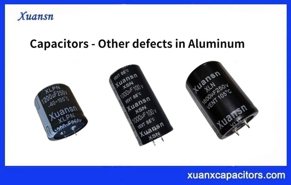
Under normal circumstances, the role of electrolytic capacitors is to filter out low-frequency signals in the current, but even for low-frequency signals, the frequency is divided into several orders of magnitude. Therefore, in order to be suitable for use at different frequencies, electrolytic capacitors are also divided into high-frequency capacitors and low-frequency capacitors (here, the high frequency is relatively speaking).
Low-frequency filter capacitors are mainly used for mains filtering or filtering after transformer rectification, and their operating frequency is the same as that of mains power at 50Hz; while high-frequency filter capacitors are mainly used for filtering after switching power supply rectification, and their operating frequency is several thousand Hz to several thousand Hz. Ten thousand Hz. When we use low-frequency filter capacitors in high-frequency circuits, due to the poor high-frequency characteristics of low-frequency filter capacitors, it has a large internal resistance and a high equivalent inductance during high-frequency charging and discharging. Therefore, in use, a large amount of heat is generated due to frequent polarization of the electrolyte. The higher temperature will vaporize the electrolyte inside the capacitor and increase the pressure in the capacitor, which will eventually cause the capacitor to bulge and burst.
The size of the power supply filter capacitor is usually designed. The front stage uses 4.7u to filter low frequencies, and the second stage uses 0.1u to filter high frequencies. The 4.7uF capacitor is used to reduce output pulsation and low frequency interference, 0.1uF The capacitor should reduce the high frequency interference caused by the instantaneous change of the load current. Generally, the more
The bigger the better, the difference between the two capacitors is about 100 times. Power filtering, switching power supply, depends on how big your ESR (equivalent series resistance of the capacitor) is, and the choice of high-frequency capacitor is best at its self-resonant frequency. Large capacitors are used to prevent surges, and the mechanism is as strong as a large reservoir’s ability to prevent floods; small capacitors filter high-frequency interference, and any device can be equivalent to a series-parallel circuit of resistance, inductance, and capacitance, which also has self-resonance. Only at this self-resonant frequency, the equivalent resistance is the smallest, so the filtering is the best!
The equivalent model of a capacitor is an inductance L, a series connection of a resistor R and a capacitor C. The inductor L is the lead of the capacitor, and the resistor R represents the active power loss of the capacitor. Therefore, it can be equivalent to the series LC circuit to find its resonant frequency. The conditions of series resonance are WL=1/WC, W=2*PI*f, and the equation f = 1/(2pi*LC) is obtained. , The minimum reactance at the center frequency of the series LC circuit is a pure resistance, so the center frequency has a filtering effect. The size of the lead inductance is different due to its thickness. The inductance of the grounding capacitor is generally about 1 MM to 10 nH, which depends on the frequency that needs to be grounded.
