1 Principle of Aluminum Electrolytic Capacitor
1.1 Principle of Aluminum Electrolytic Capacitor-And their Basic Structure
Two parallel dielectric materials that are close to and insulated from each other can be combined to store a certain amount of charge and electrical energy. The electronic components that can hold charge and are prepared using the principle of aluminum electrolytic capacitor are called capacitors. Capacitors are one of the electronic components used in large quantities in electronic equipment. They are widely used in electronic circuits such as isolated DC circuits, coupling circuits, bypass circuits, filter circuits, tuning circuits, energy conversion, and circuit control. With the development of the electronics industry, electrical products are constantly developing towards high performance, miniaturization, and integration. Capacitors are essential components in modern electrical products. They are large in size and cannot be directly implanted in large-scale integrated circuits. Therefore, the miniaturization of large-capacity capacitors, that is, high specific capacitance, has become one of the key links in the development of high-tech electrical products.
Electrolytic capacitors with positive and negative polarity can be made using a certain dielectric material with a certain thickness. Figure 1.1 schematically shows the structure of a flat plate capacitor formed by connecting a cathode dielectric material (-) with a thickness of dc and an anode dielectric material (+) with a thickness of da in series.
The capacitance formula of a flat plate capacitor is Wherein, C represents capacitance, εo and εr represent the vacuum dielectric constant and the relative dielectric constant of the dielectric material, respectively, and S and d represent the opposing area of the dielectric material and the thickness of each dielectric material, respectively.
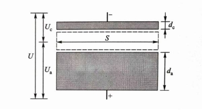 Figure 1-1 Side view of electrolytic capacitor composed of cathode dielectric material and anode dielectric material
(such as aluminum oxide film with thickness of dc and darespectively)
The dielectric material used for electrolytic capacitors should have the highest possible relative dielectric constant; dielectric materials for capacitors with excellent performance should also have the following advantages: high dielectric strength (operating voltage per unit thickness) so that it will not be broken down under high voltage; low loss angle to reduce working energy consumption and temperature rise. On the other hand, the relevant materials should also be cheap so that they can be widely and massively used. The relative dielectric constant of alumina is relatively high and insensitive to frequency, which is 9 to 10. The dielectric loss of alumina at 1MHz (tanδ, the tangent value of the loss angle δ) is less than 4×10⁻⁴, and the intrinsic dielectric loss is about 10-5. Ordinary alumina with a certain porosity can have a dielectric strength higher than 12kV/mm, and the dielectric strength of industrially prepared alumina can reach 30~40kV/mm or higher. On the other hand, alumina is cheap and the process for making aluminum capacitors is relatively mature, so aluminum capacitors have become the most widely used capacitor components.
The above is the principle of aluminum electrolytic capacitor-and the basic structure explanation
1.2 The Relationship Between the Capacitance parameters of Cathode And Anode And The Capacitor Aluminum foil
It can be seen from Figure 1.1 that if the working voltage of the capacitor as a whole is U, the voltages of cathode aluminum oxide film and anode aluminum oxide film are Uc and Ua respectively, and there are:![]()
The cathode aluminum oxide film and anode aluminum oxide film with capacitance characteristics actually form a series relationship with each other. According to the series circuit principle of capacitors and formula (1.1), the cathode aluminum oxide film capacitor Cc and the anodic aluminum oxide film capacitor Cahave the following relationship with the total capacitance C and voltage: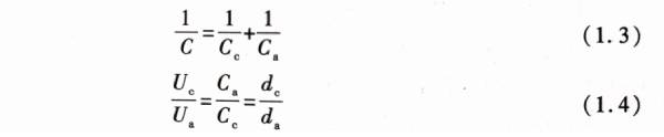 On the cathode shown in Figure 1.1, there is usually only a very thin layer of aluminum oxide film. From formula (1.1), it can be seen that when dc is very small, the cathode aluminum oxide film capacitance Ccwill be very high, which makes the value of the first term on the right side of formula (1.3) close to 0; therefore, the capacitance of the capacitor shown in Figure 1.1 mainly depends on the anodized aluminum oxide film capacitance Ca o. On the other hand, by comparing formula (1.2) and formula (1.4), it can be found that the working voltage U is borne by the cathode aluminum oxide film and the anodized aluminum oxide film respectively, and the voltages Uc and Ua borne by the two are inversely proportional to their capacitances Cc and Ca respectively. It can be seen that when the cathode aluminum oxide capacitance Cc is very high. The actual working voltage borne by the cathode aluminum oxide film is very low, and the working voltage of the capacitor is mainly borne by the anodized aluminum oxide.
The cathode and anode can be separated by electrolytic paper made by immersing a certain electrolyte, and then the cathode aluminum oxide film, electrolytic paper, and anodized aluminum oxide film parallel to each other are rolled into a cylindrical shape to make a capacitor element. The electrolyte is usually required to have low AC dielectric loss and high DC resistance. Figure 1.2 shows the winding schematic diagram of the aluminum electrolytic capacitor. After the cathode aluminum oxide film, electrolytic paper, and anodized aluminum oxide film are wound, they are placed in a metal shell, and then the cathode aluminum oxide film and the anodized aluminum oxide film are led out with conductive leads, and a usable aluminum electrolytic capacitor product is made.
Figure 1.2 Schematic diagram of aluminum electrolytic capacitor and its winding (hatched area: electrolytic paper; dotted line: metal shell)
The structural characteristics of aluminum electrolytic capacitors determine that the anodized aluminum film should have the largest possible capacitance and the highest possible withstand voltage; the sandwiched electrolytic paper can replace the cathode aluminum film and become the cathode facing the anodized aluminum film, so in fact it is mainly the anodized aluminum film that bears the dielectric function of the aluminum electrolytic capacitor. It can be seen that the production level of the anodized film determines the technical quality level of the aluminum electrolytic capacitor.
At present, it is still difficult for people to directly and large-scale use aluminum oxide to produce aluminum electrolytic capacitors in a very economical way. Usually, a metal aluminum foil of a certain thickness is first produced by forming processing, which is called a plain foil: then the surface of the aluminum foil is subjected to a specific controlled oxidation treatment to obtain a large area of a certain thickness, continuous, and voltage-resistant aluminum oxide film for the production of aluminum electrolytic capacitors. The anodized aluminum film and the cathode aluminum oxide film shown in Figure 1.2 are actually aluminum oxide films attached to the metal aluminum foil. After the metal aluminum foil is oxidized, the unoxidized aluminum foil substrate plays the role of carrying the aluminum oxide film and the conductor.
The above is the principle of aluminum electrolytic capacitor-The relationship between the capacitance parameters of the cathode and anode and the explanation of capacitor aluminum foil
1.3 Principle of Aluminum Electrolytic Capacitor-Principle of High Specific Capacitance of Capacitor Aluminum Foil
From the capacitance formula of formula (1.1), it can be seen that when the dielectric material is determined to be aluminum oxide, εo and εr are both constants. If you want to increase the capacitance of the capacitor, you need to increase the confrontation area S of the aluminum oxide film shown in Figure 1.1 or reduce the thickness d of the aluminum oxide film. When designing a capacitor, the thickness d of the aluminum oxide film cannot be reduced arbitrarily, because the aluminum oxide film needs to have a certain dielectric strength, that is, the ability to withstand a certain voltage without being broken down. When the working voltage of the electrolytic capacitor is determined, the lower limit of the oxide film thickness is determined. At this time, only by increasing the area of the dielectric film can a high capacitance be obtained. However, simply increasing the area can increase the capacitance, but it will also increase the volume of the capacitor, so it does not meet the requirements of the miniaturization of electrical products.
Through exploration and research, people have found that with the help of special electrochemical corrosion technology, a large number of tunnels of a certain size or densely distributed small pits can be corroded on the surface of aluminum foil, so that the surface area of the aluminum oxide film that can be generated on the same aluminum foil area is greatly increased; thereby, the specific capacitance of the aluminum electrolytic capacitor, that is, the capacitance per unit area of aluminum foil, can be significantly increased. As mentioned above, it is necessary to generate an aluminum oxide film on the surface of the aluminum foil to be used as a dielectric material; the thickness of the oxide film is closely related to the working voltage. The higher the voltage, the greater the thickness of the oxide film required. Therefore, according to the different working voltages of the capacitor, the size of the tunnels or holes etched on the surface of the aluminum foil is also different. High specific capacitance electrolytic capacitor aluminum foil can be divided into three categories: cathode aluminum foil, high voltage anode aluminum and low voltage anode aluminum foil. “Figure 1.3 shows a schematic diagram of the side structure of the surface of the high specific capacitance electrolytic capacitor aluminum foil after corrosion. Making tunnels or holes on the aluminum foil can greatly increase the surface area of the aluminum foil without increasing or even reducing the weight of the aluminum foil, which provides a prerequisite for significantly increasing the area of the aluminum oxide dielectric film. The cathode aluminum foil has the lowest working voltage and the highest required specific capacitance, so the holes on the surface of the cathode aluminum foil are the most dense. The high voltage anode aluminum foil has the highest working voltage, and requires a relatively coarse corrosion tunnel to accommodate a thicker aluminum oxide film. The working voltage of the low voltage anode aluminum foil is between the cathode aluminum foil and the high voltage anode aluminum, and requires slightly coarse and sparse corrosion holes.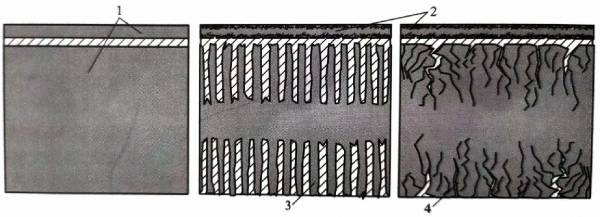
Figure 1-3 Schematic diagram of the side structure of the aluminum foil corrosion of high specific capacitance electrolytic capacitors
1-uncorroded aluminum foil, 2-cathode aluminum foil and fine corrosion pits, 3-high voltage anode aluminum foil and coarse corrosion tunnels,
4-low voltage anode aluminum foil and slightly coarse corrosion pits; hatched area: electrolyte)
After a corrosion tunnel or hole pit is produced on the surface of the aluminum foil by means of a specific corrosion technology, the tunnel wall or hole pit wall needs to be oxidized, which is called chemical formation, to form an aluminum oxide dielectric film. The aluminum foil after corrosion and chemical formation is called corrosion foil and chemical formation foil respectively. The working voltage of cathode aluminum foil is very low. Anode aluminum foil with a working voltage below 150V can usually be called low-voltage anode aluminum foil!”. With the increase of the withstand voltage value, the size of the corrosion hole pit will gradually increase, so as to make a thicker aluminum oxide film, and then make an aluminum oxide film with higher withstand voltage under the condition that the oxide film does not block the hole pit. After the working voltage is determined, the thickness d of the aluminum oxide film is also determined. Figure 1.4 shows a schematic diagram expressing this relationship. When making a high-voltage anode aluminum foil with a withstand voltage value of more than 350V, the size of the required corrosion hole pit will be significantly increased. At this time, the conventional low-voltage aluminum corrosion method is not enough to achieve uniformly distributed large-sized corrosion holes, so it is necessary to use tunnel corrosion technology for high-voltage anode aluminum foil to obtain a thick straight tunnel structure perpendicular to the aluminum foil surface.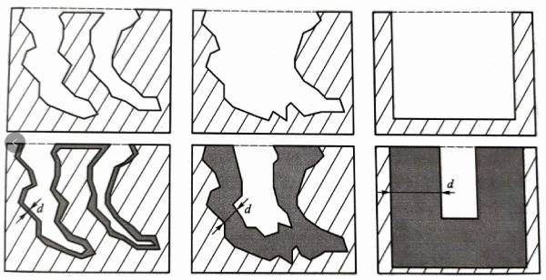
Figure 1.4 Schematic diagram of the corrosion structure of aluminum foil (above), the oxide film inside it (below) and the relationship between withstand voltage
(Left: thin oxide film aluminum foil with low withstand voltage value; middle: thick oxide film aluminum foil with high withstand voltage value;
Right: oxide film aluminum foil with high voltage resistance and thick tunnel wall. Dark area: aluminum oxide film; shadow area: aluminum substrate)
As can be seen from Figure 1.4, as the withstand voltage increases and the size of the corrosion pits or tunnels increases, not only the density of the pits and tunnels on the surface of the aluminum foil decreases, but also the increase in the total surface area of the aluminum foil, that is, the increase in the total area of the corrosion pit wall, will also decrease. This relationship between the working voltage and the corrosion pits leads to a downward trend in the maximum specific capacitance that can be achieved by the aluminum foil as the withstand voltage of the aluminum foil increases. Figure 1.5 schematically shows the approximate relationship between the withstand voltage of the anode aluminum foil and the maximum specific capacitance that can be achieved. Of course, under the condition of the same withstand voltage
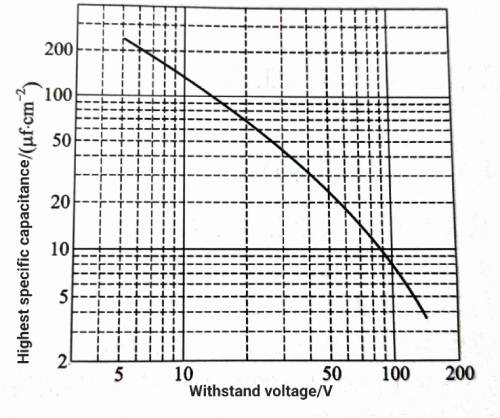
Figure 1-5 Schematic diagram of the relationship between the withstand voltage and the maximum specific capacitance of the anode aluminum foil
The specific capacitance of aluminum foil can be further improved by adjusting the internal structure and corrosion process of aluminum foil. The specific capacitance of cathode aluminum foil is usually above 500ufcm2. The specific capacitance of low-voltage anode aluminum is 10-100μf/cm 2
‘, and the specific capacitance of high-voltage anode aluminum foil is generally less than 1uf/cm 2
The dielectric strength of industrial aluminum oxide reported so far can reach above 50kV/mm[31. However, the dielectric strength of aluminum oxide is also closely related to the thickness of the aluminum oxide film; the lower the thickness of the aluminum oxide film, the higher the dielectric strength. Figure 1.6 shows the observed relationship between the dielectric strength and breakdown voltage of aluminum oxide film. As the thickness of the aluminum oxide film decreases, its breakdown voltage (aluminum oxide film thickness x dielectric strength) also decreases; but it can be inferred that when the thickness of the aluminum oxide film is reduced to a level below micrometers, its dielectric strength will reach hundreds of kilovolts per millimeter; therefore, the thickness of the oxide film on the surface of the aluminum foil of the electrolytic capacitor usually does not exceed 1um. Figure 1.6 Schematic diagram of the influence of the thickness of polycrystalline aluminum oxide film on dielectric strength (thick line) and breakdown voltage (thin line) (50Hz)
The above is the Principle of Aluminum Electrolytic Capacitor-Explanation of the principle of high specific capacitance of capacitor aluminum foil
2 Brief Description of the Basic Processing Steps of Capacitor Aluminum Foil
2.1 Principle of Aluminum Electrolytic Capacitor-Basic Production Process of aluminum Electrolytic Capacitors
Usually, a large amount of high-purity aluminum is required to manufacture aluminum for electrolytic capacitors, which refers to the anode aluminum foil that occupies the main body of aluminum in electrolytic capacitors. From the initial alumina raw material to the final production of chemical foil that can be wound into aluminum electrolytic capacitors, the relevant production process mainly includes three stages: high-purity aluminum production, light foil production, and corrosion chemical foil production. The basic process of high-purity aluminum production includes: dissolution, decomposition and calcination of bauxite to obtain alumina raw materials, electrolysis to produce primary aluminum (>99% A1), and three-layer liquid method or segregation method to produce high-purity aluminum (>99.99% AI). In the electrolytic capacitor aluminum foil production industry, primary aluminum is also collectively referred to as ordinary aluminum, and high-purity aluminum is also called refined aluminum. The basic process of light foil production includes: dissolution, batching and semi-continuous casting milling of high-purity aluminum, heating and hot rolling, cold rolling, foil rolling, cleaning, annealing, etc. The basic process of etching foil production includes: corrosion pretreatment and multi-stage corrosion, corrosion post-treatment and drying, formation pre-treatment and multi-stage formation, intermediate treatment, final formation, cleaning and drying, etc. The brief process of electrolytic capacitor aluminum foil production is shown in Figure 1.7. Figure 1-7 Schematic diagram of the simple process of electrolytic capacitor aluminum foil production
The above is the Principle of Aluminum Electrolytic Capacitor-The basic production process of aluminum electrolytic capacitors is explained
2.2 Traditional Production Method of high-Purity Aluminum
High-purity aluminum is a necessary raw material for the production of anode aluminum foil. Traditionally, it is produced by the three-layer liquid electrolytic refining method invented in 1901; Figure 1.8 shows a schematic diagram of the electrolytic cell of the three-layer liquid electrolytic refining method. The upper and lower parts of the electrolytic cell carry the electric field, the bottom is the anode, and the top is the cathode. When the electrolytic cell is working, the interior is composed of three layers of liquid. Raw aluminum and weighting agents are added from the left inlet of the electrolytic cell, usually the weighting agent is electrolytic copper. After the two are dissolved and mixed, they enter the bottom layer of the electrolytic cell to form molten high-copper raw aluminum at the anode end, which is called anode aluminum alloy, and its copper content can be 30% to 45%. The addition of different copper contents makes the density of the anode aluminum alloy liquid reach 3.0 to 3.5 g/cm 2
at high temperature, and its melting point is reduced to 550 to 590 ℃. The upper layer of the anode aluminum alloy liquid is the electrolyte layer, which is mainly composed of vapors such as NaF, CaF2, AlF3, BaF2, or chlorides such as NaCl, BaCI2, or fluorine chlorides [3], and its density is 2.5-2.7 g/cm3. Above the electrolyte layer is the molten high-purity aluminum liquid layer, which has a density of about 2.3 g/cm 3 at high temperature and is at the cathode end. It can be seen that the density of each of the three layers of liquid in the electrolytic cell determines that they can maintain a stable stratified distribution state during the high-purity aluminum production process.
Under high temperature and electric field, the Al atoms in the anode aluminum alloy liquid at the bottom of the electrolytic cell will lose electrons and show electrochemical dissolution, that is, the reaction A1 (liquid) -3e––AI3+ will occur. At the same time, under the action of the electric field, AI 3+ will pass through the electrolyte layer and enter the high-purity aluminum liquid layer, and obtain electrons at the cathode and be reduced to Al atoms, that is, the reaction AI3+ +3e– -→Al (liquid).
In addition to a large number of copper atoms, the anode aluminum alloy also contains many other impurity atoms of the original aluminum. Among them, Cu, Si, Fe and other atoms have higher electrode potentials than A1 atoms, so they will not undergo electrochemical dissolution.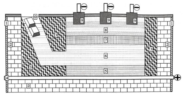
Figure 1.8 Schematic diagram of the electrolytic cell of the three-layer liquid electrolytic refining method
(0-aluminum ingot and electrolytic copper inlet, 1-electrolytic cell shell, 2-refractory bricks, 3-magnesia brick lining,
4-anode electrode, 5-anode carbon cell bottom, 6-copper-containing molten anode aluminum,
7-fluoride, chloride or fluoride chloride electrolyte, 8-molten high-purity aluminum liquid, 9-graphite cathode electrode)
The electrochemical dissolution behavior is described above and it always remains in the anode aluminum alloy liquid. In addition, the electrode potential of atoms such as Na, Ca, and Mg is lower than that of Al atoms. Although it is easy to form Na+, Ca2+, and Mg2+ and enter the electrolyte layer, the lower electrode potential is not conducive to their release of electrons in the high-purity aluminum liquid layer, so they will remain in the electrolyte layer. The three-layer liquid electrolytic refining method utilizes the above differences in electrochemical properties between Al atoms and other atoms, thereby realizing the production of high-purity aluminum.
Al atoms in the anode aluminum alloy liquid continuously pass through the electrolyte layer, reducing the aluminum content in the alloy; the aluminum content in the anode aluminum alloy liquid can be supplemented by continuously adding raw aluminum ingots from the population, so that its composition is kept within the set reasonable range. At the same time, high-purity aluminum liquid is continuously absorbed from the high-purity aluminum liquid layer and cast into high-purity aluminum ingots. In this way, the production process from raw aluminum to high-purity aluminum can be continuously implemented.
In the above production process of high-purity aluminum, the huge difference in copper content between the anode aluminum alloy liquid and the high-purity aluminum liquid will cause 0.35-0.40V concentration polarization and voltage drop in the electrolyte layer. All Al atoms in the anode aluminum alloy liquid must overcome the concentration polarization voltage under the action of the external electric field, pass through the electrolyte layer and transform into high-purity aluminum. Therefore, the production of high-purity aluminum by the three-layer liquid electrolytic refining method is a high-energy consumption process.
The above is the principle of aluminum electrolytic capacitor -The traditional production method of high-purity aluminum is explained.
2.3 Processing of light foil
The processing of electrolytic capacitor aluminum foil mainly involves the production process from high-purity aluminum to corrosion processing. Figure 1.9 shows a schematic diagram of some major processes in the processing of foil. In the semi-continuous casting production process, the high-purity aluminum ingot is first dissolved, and then the appropriate ingredients and micro-components are adjusted according to the composition design. Finally, during the pouring, a 200-250 mm thick semi-continuous casting slab is made by the continuous condensation process in the finisher [Figure 19 (a)]. The production of electrolytic capacitor aluminum foil has very strict requirements on its purity. The semi-continuous casting production process is easy to cause different degrees of contamination on the surface of the slab. Therefore, before rolling processing, it is necessary to use a double-sided milling machine to remove a certain thickness of the billet on the upper and lower rolling surfaces of the semi-continuous casting slab. The uniformity of the trace alloying elements inside the aluminum foil of electrolytic capacitors will also have an important impact on the product performance. Therefore, before hot rolling [Figure 1.9 (b)], it is necessary not only to perform conventional hot rolling heating on the semi-continuous casting slab, but also to specially design the heating process so as to simultaneously implement homogenization annealing to promote the uniform distribution of trace elements inside the slab. Hot rolling usually processes the semi-continuous casting slab into a hot-rolled plate with a thickness of 6 to 8 mm. The hot rolling and cold rolling of the aluminum foil of electrolytic capacitors [Figure 1.9 (c)] are not only to obtain the thickness of the final aluminum foil, but also to play an important role in adjusting the internal structure of the aluminum foil, which is obviously different from ordinary aluminum processing. Cold rolling includes conventional cold rolling and foil rolling. The thickness of aluminum foil after conventional cold rolling is usually less than 1 mm; according to the requirements of different product varieties and specifications, the final thickness of the aluminum foil after foil rolling is mostly in the range of 0.015 to 0.12 mm. Most anode aluminum foils need to be used in a non-work hardened state, so annealing is required after cold rolling. At present, vacuum annealing technology is mostly used in China to treat aluminum foil [Figure 1.9 (d)] to prevent excessive oxidation of the aluminum foil surface. During the cold rolling process, a large amount of rolling oil and lubricants come into contact with the aluminum foil surface and cause surface stains. After cold rolling, many foreign substances such as aluminum chips and dust will also adhere to the surface. These defects may react to a certain extent on the surface of the aluminum foil during high-temperature annealing, and have an adverse effect on subsequent corrosion and chemical processing. Therefore, the cold-rolled aluminum foil needs to be cleaned before annealing!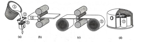
Figure 1.9 Schematic diagram of the main processes of light foil processing:
(a) Semi-continuous casting; (b) Hot rolling; (c) Cold rolling and foil rolling;
(d) Vacuum annealing (1-casting ladle, 2-high-purity aluminum liquid, 3-crystallizer, 4-semi-continuous casting slab, 5-cold-rolled aluminum foil roll)
The above is the principle of aluminum electrolytic capacitor-Explanation of the processing of light foil
2.4 Corrosion And Chemical Processing of Aluminum Foil
Corrosion and chemical processing of aluminum foil are the final key processes for obtaining aluminum foil for high specific capacitance electrolytic capacitors. This processing stage is completed under the electrochemical conditions of appropriate electric field, temperature and corrosive medium.
Figure 1.10 shows the schematic diagram of the main process of aluminum foil corrosion process [5-6]. In the pretreatment stage, alkaline washing is often used to remove oil stains, natural oxide film, etc. on the surface of aluminum foil to provide a suitable surface state for the corrosion process. Then the aluminum foil is subjected to corrosion pore treatment, that is, the starting points of corrosion pores are uniformly distributed on the flat surface of the aluminum foil by electrochemical means. The lower the pressure resistance requirement of the aluminum foil, the higher the required pore density. After pores are formed, the generated corrosion pores need to be properly expanded according to the pressure resistance requirement of the aluminum foil, including the expansion of the corrosion pore diameter and the extension of the pore depth, so as to further increase the surface area of the aluminum foil. After appropriate post-treatment, the corroded foil is obtained.
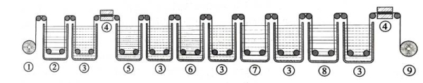
Figure 1.10 Schematic diagram of the main processes of aluminum corrosion process
(1-unwinding, 2-pretreatment, 3-cleaning, 4-drying, 5-primary pore formation, 6-secondary pore formation, 7-electrolytic pore expansion, 8-post-treatment, 9-foil collection)
Figure 1.11 shows the main process diagram of the high-voltage anode corrosion foil formation process. In the pretreatment stage, it is necessary to remove surface impurities, surface residues, etc., and a certain surface electrochemical reaction occurs to provide a suitable surface state for the formation process. Subsequently, the corrosion foil is subjected to multi-stage formation treatment, and the formation voltage of the latter stage is usually higher than that of the previous stage; the thickness and withstand voltage level of the oxide film after formation are related to the working voltage of the capacitor. Appropriate intermediate treatment needs to be added during the formation process; sometimes appropriate high-temperature treatment needs to be added to adjust the crystal structure and density of the formed oxide film. After proper post-treatment, the formed foil that can be used for winding capacitors is obtained.
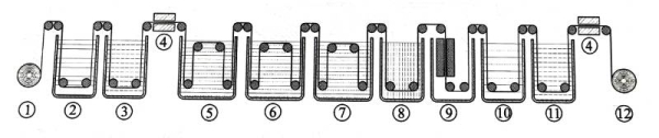
Figure 1-11 Schematic diagram of the main process of high-voltage anode corrosion foil formation process
(1-unwinding, 2-pretreatment, 3-cleaning, 4-drying, 5-primary formation, 6-secondary formation, 7-tertiary formation, 8-intermediate treatment, 9-high temperature treatment, 10-end formation, 11-post-treatment, 12-foil collection)
For different product varieties and specifications of electrolytic capacitors, the process and process links of related electrochemical treatment will be very different. Figures 1.10 and 1.11 are just schematic descriptions of some of the process steps that may be involved in the relevant process. For the specific process, please pay attention to the information on Xuansn Electronics’ related website.
Summary:
The above is the principle of aluminum electrolytic capacitor -An explanation of the corrosion and chemical processing of aluminum foil
For more information about capacitors, please click:https://xuansncapacitor.com/