With the acceleration of the upgrading of digital electronic products, the production and consumption of the capacitor industry will increase accordingly. There are many types of capacitors, and professionals in the circuit industry often use capacitor symbols and graphics to judge their properties. So today we will talk about how to draw the capacitor symbol and the detailed explanation of the capacitor symbol and graphics.
 =
=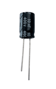
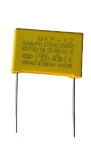
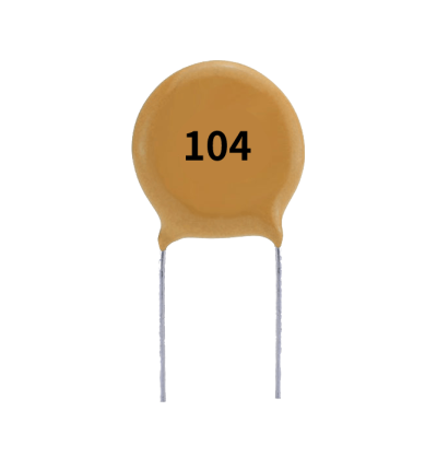
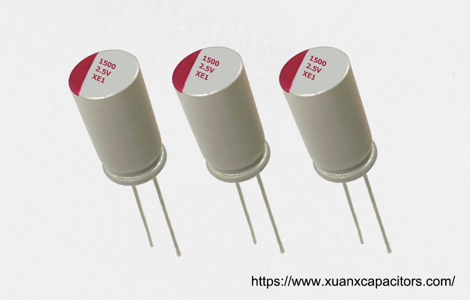
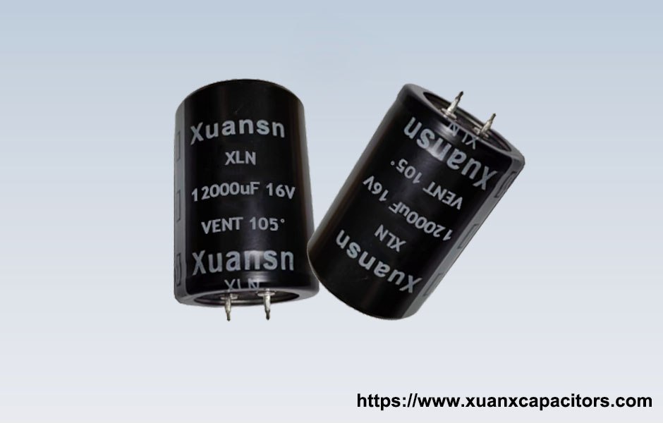
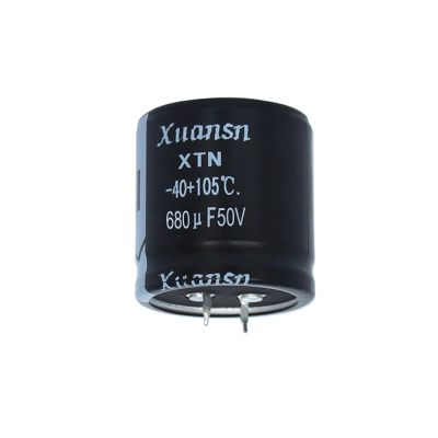
The above are some physical pictures of capacitors, we can see that the listed capacitors have pins.
How to draw the capacitor symbol?
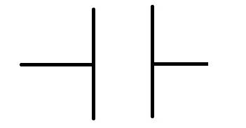
The drawing method of the capacitor symbol is actually very simple: it generally consists of two horizontal lines plus two parallel vertical lines. Different types of capacitors have different drawing methods, but they remain the same.
The horizontal lines at both ends indicate: the two pins of the capacitor are connected with other circuits to form an electronic circuit;
Two parallel lines mean: A capacitor embodies its internal principle in an electronic circuit diagram.
How to classify the circuit symbols of capacitors in the circuit?
- The circuit symbols of capacitors in circuits are typically classified based on their general type or function. Here are the commonly used classifications for circuit symbols of capacitors:Fixed Capacitors: Fixed capacitors have a specific capacitance value that is determined during the manufacturing process. The circuit symbols for fixed capacitors usually represent their basic shape and type, without indicating specific capacitance values. Examples of fixed capacitors include ceramic capacitors, film capacitors, and electrolytic capacitors. The symbols for fixed capacitors can vary slightly depending on the specific type, but they generally reflect the overall shape of the capacitor.The following are common fixed capacitor symbols:
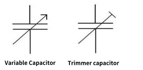
 Variable Capacitors: Variable capacitors, also known as tuning capacitors or trimmers, have adjustable capacitance values. These capacitors are used in applications where the capacitance needs to be changed or fine-tuned. The circuit symbol for a variable capacitor typically includes additional components, such as a mechanical dial or a set of curved lines, to indicate adjustability.Below are the common variable capacitor symbols:
- Polarized Capacitors: Polarized capacitors are a specific type of capacitor that has a positive and negative terminal. They need to be connected in the correct polarity for proper operation. Electrolytic capacitors and tantalum capacitors are common examples of polarized capacitors. The circuit symbol for polarized capacitors includes polarity indicators, such as a straight line and a curved or plus-shaped line, to represent the positive and negative terminals.Below are common polarized capacitor symbols:

It’s important to consult the documentation or specifications of the specific capacitor being used to ensure you are using the correct circuit symbol for that particular type. The circuit symbols serve as a standardized representation to aid in circuit design and understanding the connections and characteristics of the capacitors within the circuit.
Now that we know that a capacitor has positive and negative poles, how do we distinguish the positive and negative poles of a capacitor? Let’s move on.
How to distinguish the positive and negative poles of electrolytic capacitors?
First of all, let’s take a look at how to distinguish the positive and negative poles of conventional electrolytic capacitors.
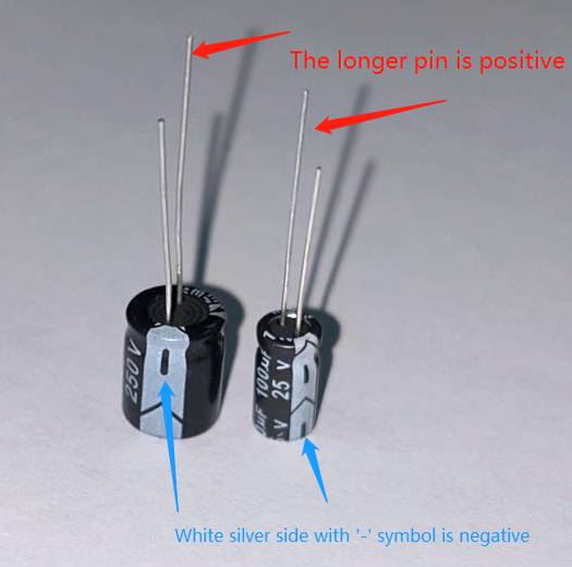
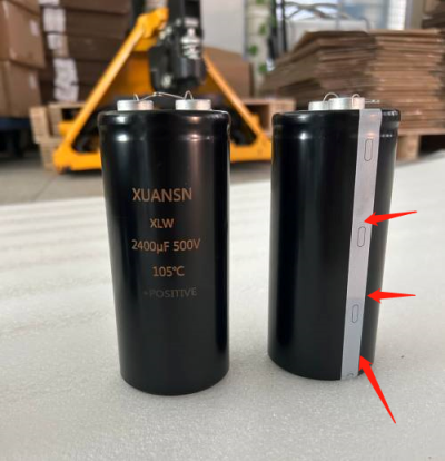
Snap in Capacitor
The first way to judge is to look at the white silver edge. The one with the character ‘–‘ is the negative pole. The second is to look at the embossing of the contacts. Most of them are various embossings on the negative pole. Some manufacturers will also press the positive and negative marks on the contacts.
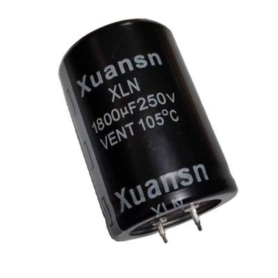
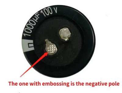
Screw Terminal Capacitor
Still look at the silver lace. The one with ‘–‘ is the negative pole. The second is to look at the screw terminals on the top. Most manufacturers have marked the positive and negative poles.

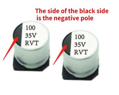
Chip Aluminum Electrolytic Capacitors
This is best identified, the end with the black half is the negative pole.
Summarize
Capacitors can be classified as polarized or non-polarized, and their circuit symbols differ accordingly. Electrolytic capacitors, as polarized capacitors, require correct connection to the positive and negative terminals, while ceramic capacitors and film capacitors, as non-polarized capacitors, can be freely connected in the circuit.
